Esta versión puede contener ediciones incorrectas. Cambiar a la última instantánea verificada.
Qué necesitas
-
-
Deslice la lengüeta en la parte posterior de su GoPro para abrir la tapa de la batería
-
-
Este paso está sin traducir. Ayuda a traducirlo
-
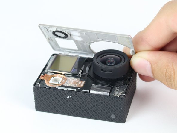
Use the plastic opening tool to remove the faceplate.
-
There is some adhesive and clips so be careful and the faceplate should pop right off.
-
-
Este paso está sin traducir. Ayuda a traducirlo
-
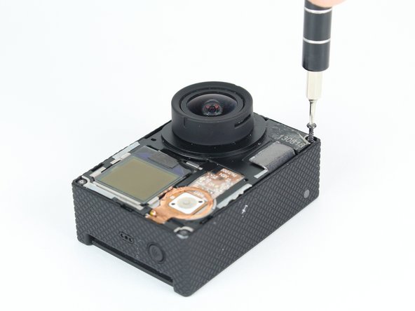
Now that the faceplate is off, it is time to remove the 4 screws on each corner.
-
Use the T4 tool bit from the iFixit toolkit in order to remove the 4 screws on each corner.
-
-
-
Este paso está sin traducir. Ayuda a traducirlo
-
Note: Make sure you remove the door cover of the USB, mini HDMI, and SD port before. Separating the motherboard will be easier.
-
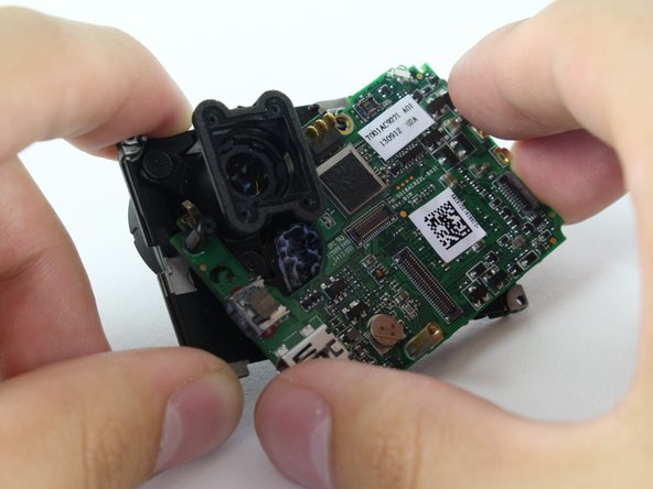
Using the plastic opening tool, slowly pry open the motherboard assembly.
-
-
Este paso está sin traducir. Ayuda a traducirlo
-
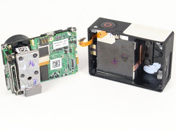
Use the spudger to gently pry off the connector of the housing to the motherboard.
-
You should now have the motherboard assembly and the housing separated.
-
-
Este paso está sin traducir. Ayuda a traducirlo
-
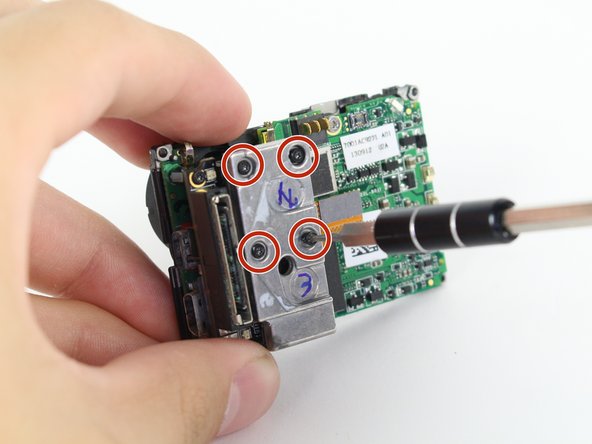
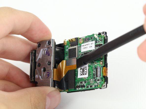
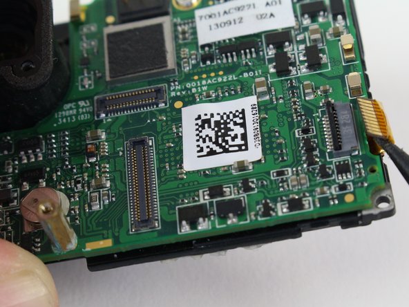
Use the spudger to remove the heat shield tape and detach the image sensor from the motherboard.
-
Using the T4 Torx toolbit, remove the 4 screws that connect the sensor to the lens.
-
Remove the silver connector of the image sensor from the motherboard using the spudger to pry it off.
-
-
Este paso está sin traducir. Ayuda a traducirlo
-
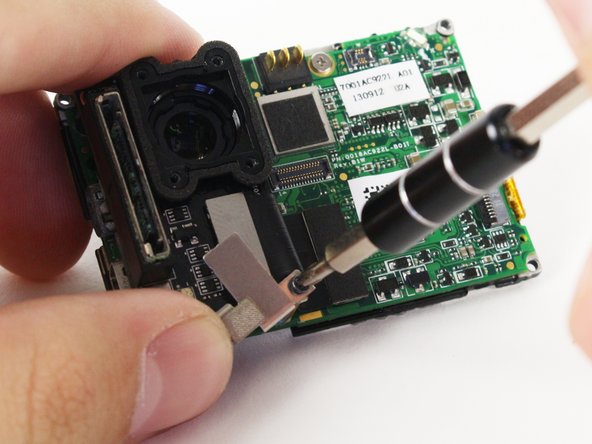
The media adapter is attached to the motherboard via 3 screws:
-
x1 T4 Torx
-
x2 Phillips #00
-
With a little prying, use the spudger to detach the media adapter's connector from the motherboard.
-
-
Este paso está sin traducir. Ayuda a traducirlo
-
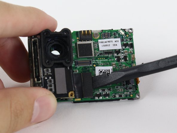
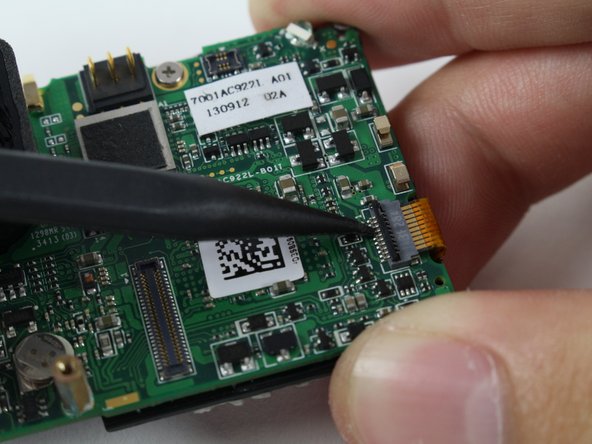
Use the spudger to lift the black tab up to unlock.
-
Then remove LCD screen connector by sliding out.
-
-
Este paso está sin traducir. Ayuda a traducirlo
-
Using the Phillips head bit, remove the silver screw near the the top edge of the board.
-
Separate the LCD assembly by pulling away the motherboard.
-
-
Este paso está sin traducir. Ayuda a traducirlo
-
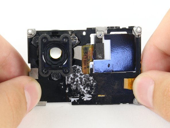
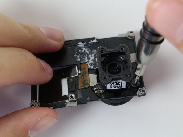
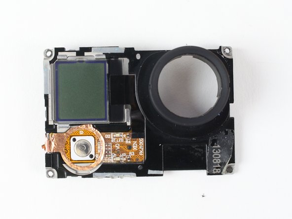
There are 3 Phillips #00 screws holding the lens onto the LCD housing that need to be removed.
-
-
Este paso está sin traducir. Ayuda a traducirlo
-
Carefully remove the camera lens from the LCD Housing.
-
Now you have the LCD housing removed!
-


Cancelar: No complete esta guía.
5 personas más completaron esta guía.
Equipo

Cal Poly, Team 24-7, Lancaster Spring 2015 Miembro de Cal Poly, Team 24-7, Lancaster Spring 2015
CPSU-LANCASTER-S15S24G7
3 Miembros
21 Guías creadas