Qué necesitas
-
Este paso está sin traducir. Ayuda a traducirlo
-
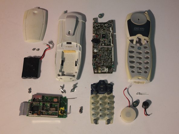
This is a teardown of a GE 27990G3 cordless phone system from 2001. Sadly, while it still works, its 2.4 GHz wireless transmitter interferes with WiFi.
-
-
Este paso está sin traducir. Ayuda a traducirlo
-
Part I: The Handset.
-
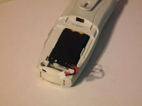
Remove the battery door on the back.
-
-
Este paso está sin traducir. Ayuda a traducirlo
-
Use needlenose pliers to disconnect the battery connector.
-
The battery is a 3.6V Nickel-Cadmium rechargeable battery made up of 3 AAA-sized cells
-
-
Este paso está sin traducir. Ayuda a traducirlo
-
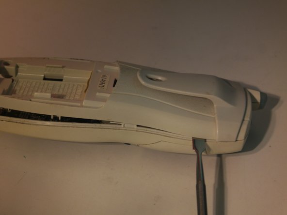
Remove 2 phillips screws inside the battery compartment.
-
-
Este paso está sin traducir. Ayuda a traducirlo
-
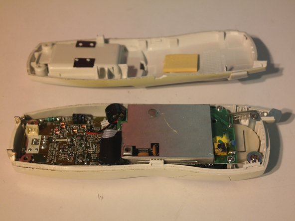
After some aggressive spudgering (the pictures make it look much easier), the back of the case can be removed.
-
-
Este paso está sin traducir. Ayuda a traducirlo
-
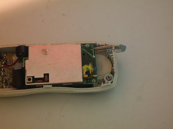
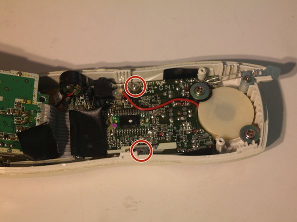
Remove 2 screws on what appears to be the wireless board.
-
-
Este paso está sin traducir. Ayuda a traducirlo
-
The wireless board can be flipped up, but is still attached to the main board by a short ribbon cable.
-
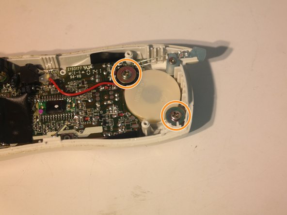
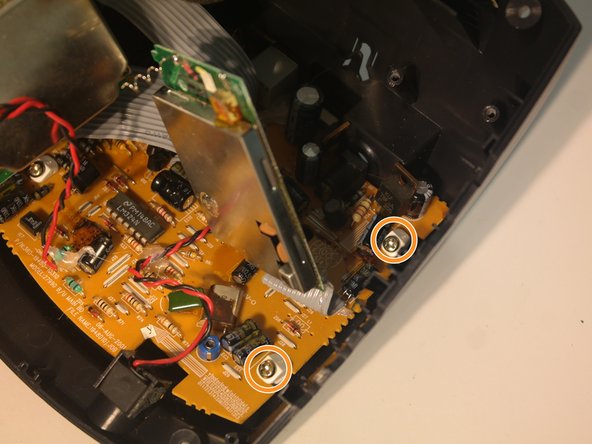
Remove 2 screws on the main board.
-
Remove 2 screws on the speaker.
-
-
Este paso está sin traducir. Ayuda a traducirlo
-
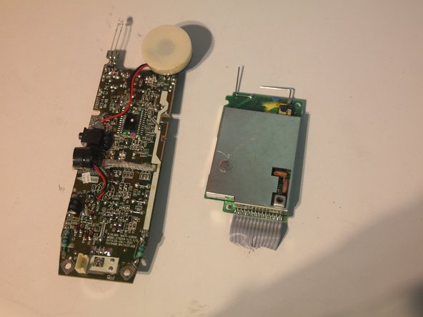
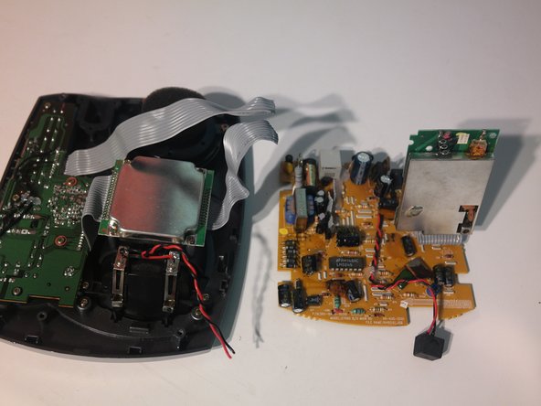
The mainboard assembly can now be removed from the front case.
-
-
Este paso está sin traducir. Ayuda a traducirlo
-
The wireless board is attached by a soldered and hot-glued in ribbon cable, which must be cut off to remove.
-
-
Este paso está sin traducir. Ayuda a traducirlo
-
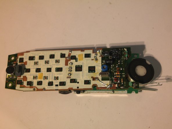
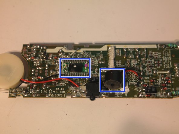
Components on the main board:
-
Speaker
-
Message indicator LED
-
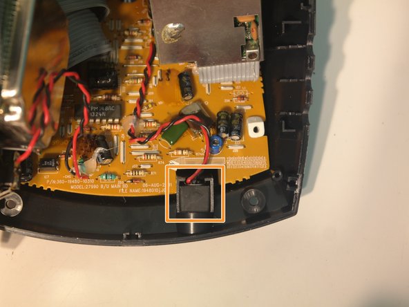
Ringer switch
-
Electret microphone
-
Unknown potted 'Blob' IC
-
Piezo buzzer for ringer
-
-
Este paso está sin traducir. Ayuda a traducirlo
-
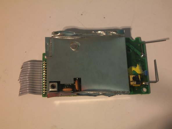
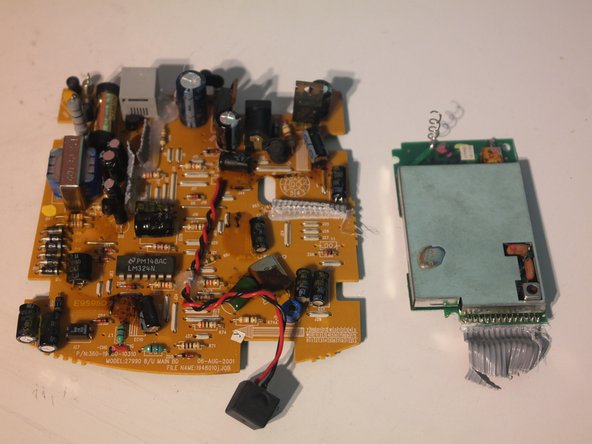
Whoever designed the wireless module really didn't want anyone to know what was inside. The very thick EMI shield is soldered, crimped, and epoxied on.
-
The shield took about 20 minutes to remove with diagonal cutters, 2 pairs of pliers, and 3 metal spudgers.
-
Needless to say, the shield is irreversibly damaged and the wireless module will probably never work again.
-
-
Este paso está sin traducir. Ayuda a traducirlo
-
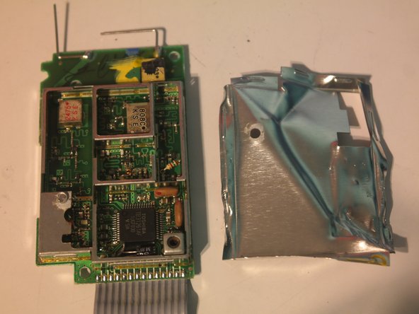
Components inside the wireless module:
-
Toshiba TB31261AF cordless telephone RF chip
-
Ceramic resonators
-
Unidentified square ceramic components with 2 cylindrical holes in them horizontally (anyone who has an idea what they are, please comment.)
-
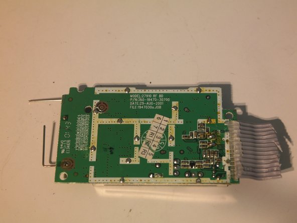
The back of the board says that it was manufactured on August 29, 2001, making the phone 14 years old at the time of writing.
-
Interestingly, the Toshiba TB31261AF is designed for a 900MHz cordless telephone, but this is a 2.4GHz model.
-
-
Este paso está sin traducir. Ayuda a traducirlo
-
Repairability score: 6/10
-
Phone is held together with only phillips screws.
-
Battery, the most likely part to fail, is a standard component and is easily replaceable.
-
Case is difficult to open.
-
Wireless module is very hard to replace and impossible to repair.
-
All wires (except for the battery) are soldered to the circuit board instead of using connectors.
-
-
-
Este paso está sin traducir. Ayuda a traducirlo
-
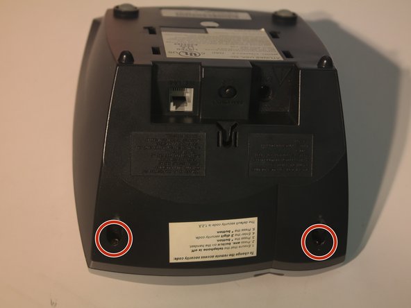
Part II: The Secondary Base Station
-
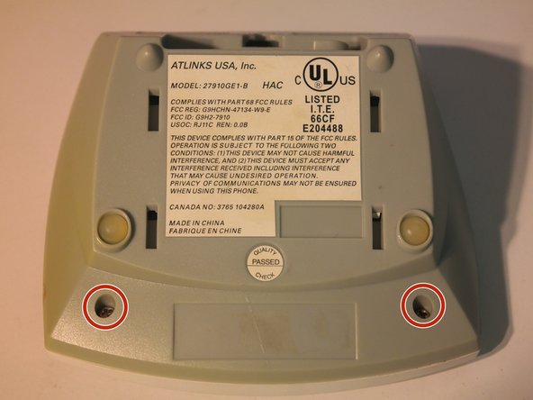
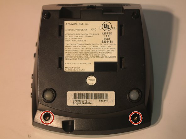
Remove 2 phillips screws on the bottom.
-
-
Este paso está sin traducir. Ayuda a traducirlo
-
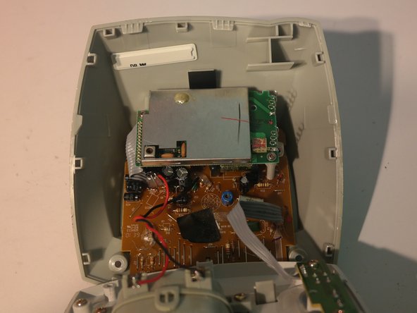
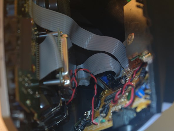
Just like in the handset, the wireless module is connected to the main board with a soldered ribbon cable. I'm sensing a theme here.
-
Remove 2 screws that hold down the main board.
-
-
Este paso está sin traducir. Ayuda a traducirlo
-
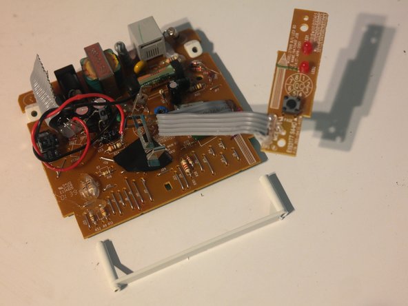
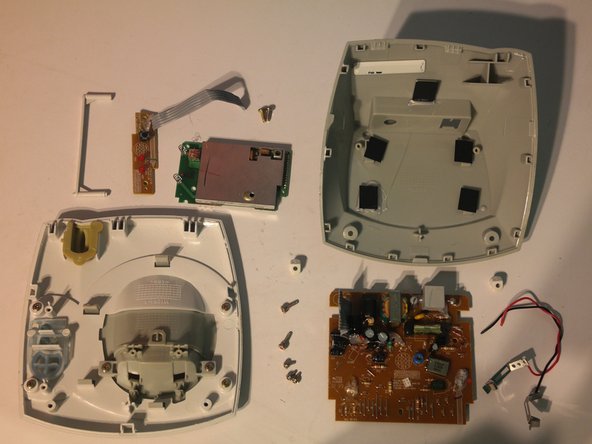
The main circuit board can be removed from the bottom case.
-
Remove 4 screws holding in the button board and charging contacts from the top case.
-
-
Este paso está sin traducir. Ayuda a traducirlo
-
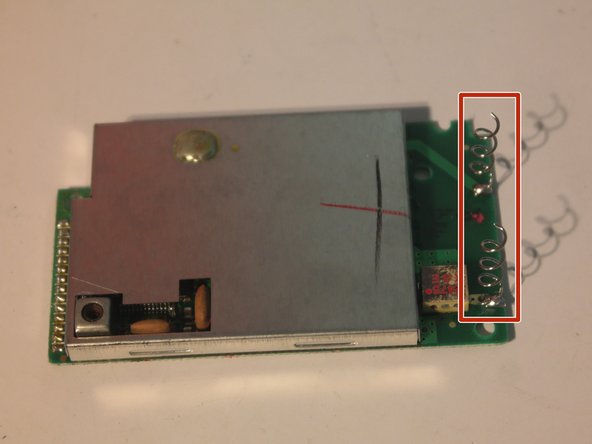
The wireless module can be cut away from the logic board.
-
This wireless module is identical to the one in the handset except for the fact that it used coiled wires instead of straight wires for antennas.
-
-
Este paso está sin traducir. Ayuda a traducirlo
-
Remove 2 screws to remove the support for the wireless module.
-
The plastic pieces used to hold down the board can also be removed.
-
-
Este paso está sin traducir. Ayuda a traducirlo
-
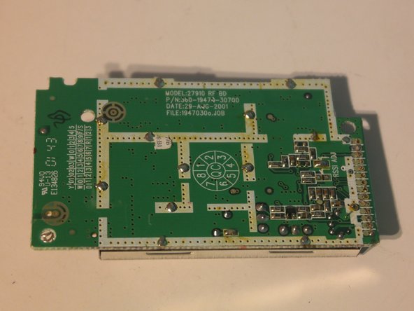
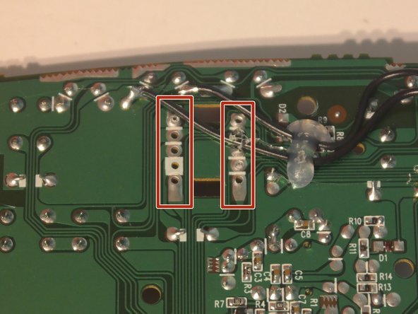
The button board contains a lonely button, 2 LEDs, and is connected with a soldered ribbon cable reinforced with hot glue.
-
This board appears to have been manufactured on April 17, 2001.
-
-
Este paso está sin traducir. Ayuda a traducirlo
-
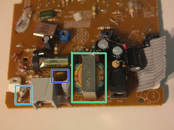
Components on the main board:
-
4 MHz crystal
-
Variable capacitor
-
Small audio transformer
-
Miniature fuse
-
Varistor for surge protection
-
This board was manufactured on September 3, 2001.
-
-
Este paso está sin traducir. Ayuda a traducirlo
-
Repairability Score: 4/10
-
Secondary base station is assembled with only phillips screws.
-
Circuit boards use mainly through-hole parts, so repair of individual components is easier.
-
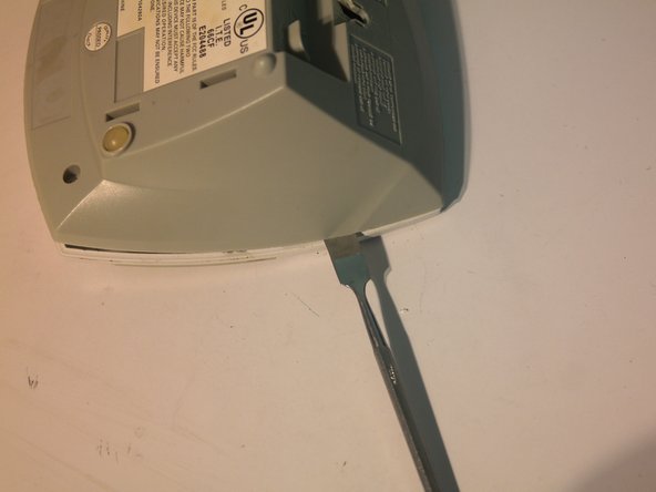
Case requires lots of spudgering to open.
-
Removing the board requires a long screwdriver.
-
Wireless module is very hard to replace and impossible to repair.
-
All wires and ribbon cables are soldered to the board and reinforced with hot glue.
-
-
Este paso está sin traducir. Ayuda a traducirlo
-
Part III: The Main Base Station
-
First step: remove 4 screws.
-
-
Este paso está sin traducir. Ayuda a traducirlo
-
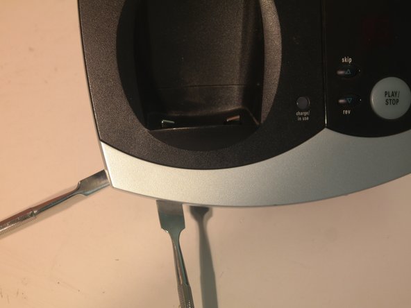
The case for the main base station can be opened, but it requires 2 spudgers and much more force than the other one.
-
Remember how I said soldered ribbon cables were becoming a theme here? I was right.
-
-
Este paso está sin traducir. Ayuda a traducirlo
-
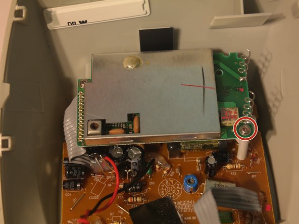
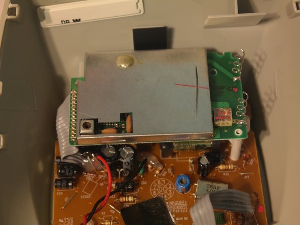
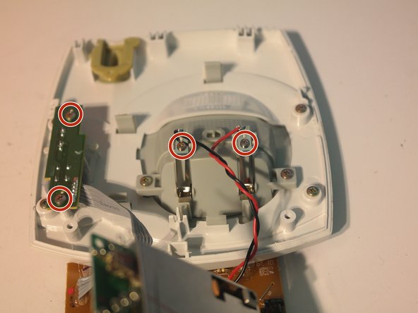
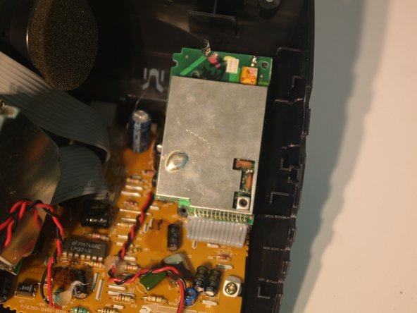
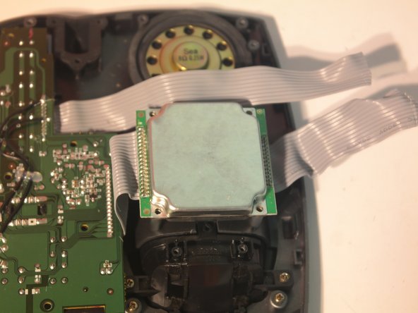
Remove 2 screws holding down the wireless module.
-
Remove 2 more screws holding down the plastic pieces attached to the circuit board.
-
-
Este paso está sin traducir. Ayuda a traducirlo
-
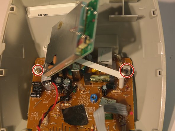
Remove another 2 screws on the other side of the board.
-
Remove the microphone from its holder.
-
-
Este paso está sin traducir. Ayuda a traducirlo
-
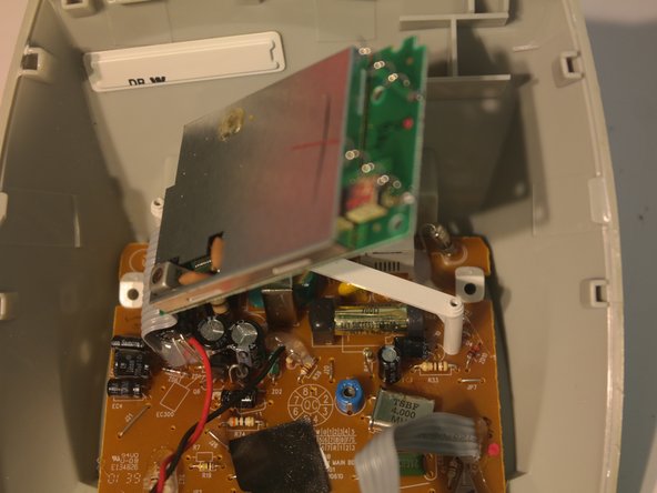
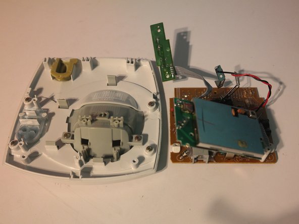
In order to remove the board from the bottom case, you have to carefully reach in and free each one of the plastic pieces attached to the board from a clip on the bottom case.
-
All of the cables to the main board can now be cut and the wireless module can be cut off of the main board.
-
-
Este paso está sin traducir. Ayuda a traducirlo
-
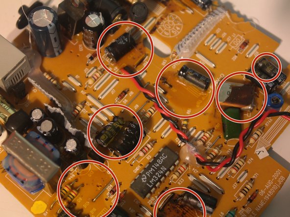
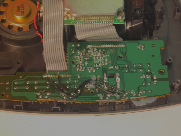
The main board in the base station has patches of an unknown yellowish-brown substance on it that appears to be some kind of weak adhesive, and it seems to be scattered in no obvious pattern.
-
-
Este paso está sin traducir. Ayuda a traducirlo
-
Remove 2 screws to remove the charging contacts in the upper case.
-
-
Este paso está sin traducir. Ayuda a traducirlo
-
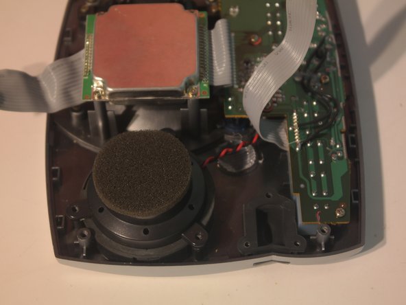
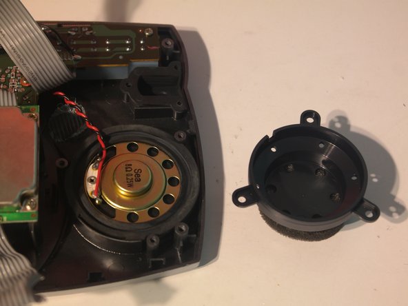
Remove 3 screws to remove the speaker cover.
-
This speaker cover appears to have been designed to accomodate both a low-profile speaker and a speaker with a larger magnet on the back.
-
-
Este paso está sin traducir. Ayuda a traducirlo
-
The upper case board can be removed by removing 5 screws.
-
-
Este paso está sin traducir. Ayuda a traducirlo
-
The entire top case assembly can be removed from the printer after using a spudger to free the large buttons from clips in the top case.
-
-
Este paso está sin traducir. Ayuda a traducirlo
-
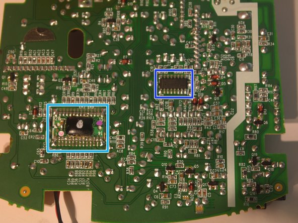
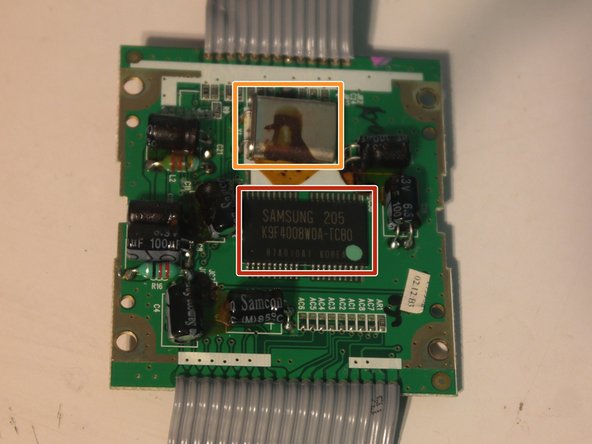
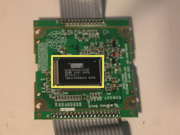
So what is inside the mysterious metal box?
-
Samsung K9F4008W0A-TCB0 512x8 Kb (512 KB) flash memory (designed for digital audio recording)
-
Crystal oscillator, covered in the same unusual substance found on the main board.
-
Unknown IC D16529CAC11CQC. Googling it turns up nothing that makes any sense.
-
This board is probably where the messages are stored.
-
-
Este paso está sin traducir. Ayuda a traducirlo
-
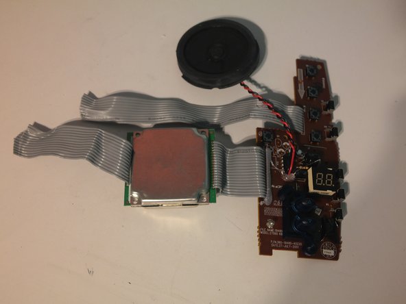
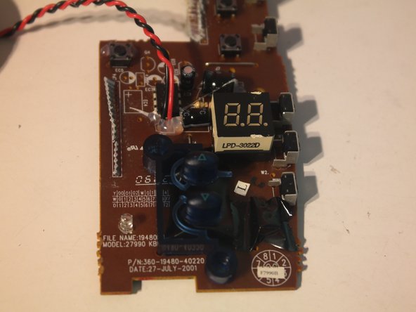
The major components on the top case board:
-
Dual 7-segment display
-
LM386 audio amplifier
-
Message indicator LED
-
This board was manufactured on July 27, 2001.
-
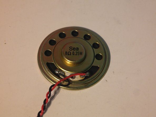
The speaker is a standard 2" low profile 8 ohm 0.25 watt speaker.
-
-
Este paso está sin traducir. Ayuda a traducirlo
-
All of the boards in this phone system have terrible solder quality. I was able to cleanly remove the 7-segment display, about 20 capacitors, 3 voltage regulators, 1 transformer, and 2 crystal oscillators without damaging them using needle nose pliers.
-
-
Este paso está sin traducir. Ayuda a traducirlo
-
Repairability Score: 3/10
-
Base station is only held together with phillips screws.
-
Circuit boards use mainly through-hole parts, so repair of individual components is easier.
-
Removing the top circuit board is difficult because the buttons are attached to the top case with clips.
-
Opening the case requires 2 metal spudgers and a lot of force.
-
Removing the bottom circuit board is difficult because the case is still attached with soldered ribbon cables.
-
Wireless module is very hard to replace and impossible to repair.
-
All wires and ribbon cables are soldered to the board and reinforced with hot glue.
-
-
Este paso está sin traducir. Ayuda a traducirlo
-
Overall repairability score: 5/10
-
The handset battery, the most likely part to fail, is a standard component and is easily replaceable.
-
Circuit boards use mainly through-hole parts, so repair of individual components is easier.
-
Entire phone is held together with phillips screws
-
Cases are difficult to open and require heavy spudgering.
-
Most parts were not designed to be repaired.
-
All wires and ribbon cables are soldered to the board and reinforced with hot glue.
-