Qué necesitas
-
Este paso está sin traducir. Ayuda a traducirlo
-
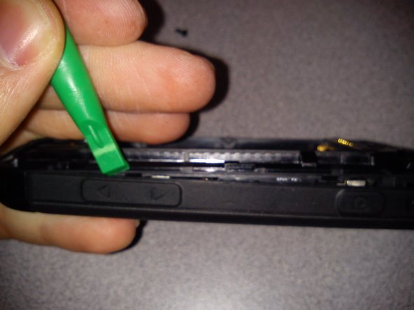
After all 6 screws have been removed, start by using a plastic pry tool to separate the back panel from the side frame.
-
Continue along the side near the volume buttons slowly seperating the back panel from the frame.
-
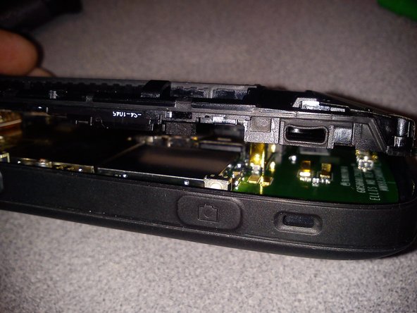
Once the back panel has been seperated from the frame slowly take it off, being careful not to break any plastic parts/clips.
-
Keep track of your screws.
-
-
Este paso está sin traducir. Ayuda a traducirlo
-
Unscrew the 2 Philips head (+) screws to remove the camera flash module.
-
This unit has a broken micro usb charging port.
-
-
-
Este paso está sin traducir. Ayuda a traducirlo
-
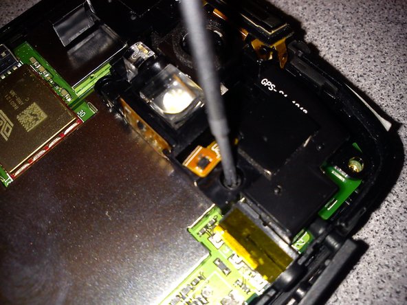
After the camera module has been removed pull up any tape covering the digitizer flex cable.
-
-
Este paso está sin traducir. Ayuda a traducirlo
-
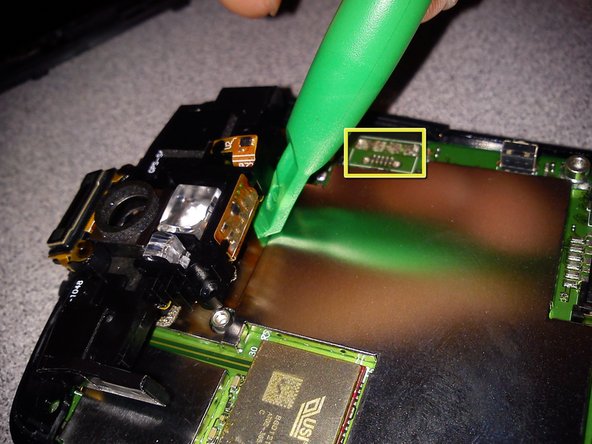
Slowly lift the logic board out of the frame starting at the bottom of the phone.
-
-
Este paso está sin traducir. Ayuda a traducirlo
-
Pry off metal cap to remove shielding to access LCD flex cable.
-
-
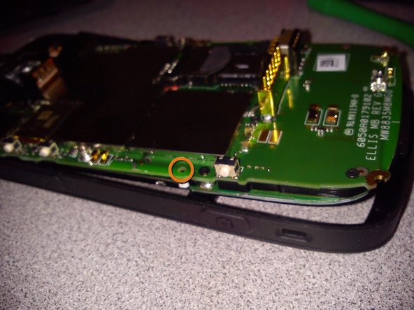
Este paso está sin traducir. Ayuda a traducirlo
-
Use a flat head screwdriver to flip up the FPC connector.
-


Un comentario
This disassembly guide was provided by Wires Computing Electronics Repair. for help with any repairs in Burlington Vermont please visit: www.wirescomputing.com