Esta versión puede contener ediciones incorrectas. Cambiar a la última instantánea verificada.
Qué necesitas
-
Este paso está sin traducir. Ayuda a traducirlo
-
Use your finger tips to pinch the damaged propeller.
-
Twist the propeller counterclockwise and pull up to remove.
-
-
Este paso está sin traducir. Ayuda a traducirlo
-
Remove the eight 7 mm hex screws by turning counterclockwise with a 2 mm hex bit.
-
-
Este paso está sin traducir. Ayuda a traducirlo
-
Pry the paper covering off the four corners with a metal spudger.
-
-
Este paso está sin traducir. Ayuda a traducirlo
-
Remove the twelve 8.7 mm hex screws with a 2 mm hex bit from the motor bases.
-
-
-
Este paso está sin traducir. Ayuda a traducirlo
-
Flip the drone on its back
-
Remove the eight 4.5 mm hex screws by turning them counterclockwise with a 1.5 mm hex bit.
-
Separate the mesh from the drone by pulling up gently and rocking left to right.
-
-
Este paso está sin traducir. Ayuda a traducirlo
-
Remove two 1.2mm screws using the JIS #000 bit from the camera cable retaining bracket.
-
-
Este paso está sin traducir. Ayuda a traducirlo
-
Lift the camera connector at one end with your hand and remove the mesh.
-
-
Este paso está sin traducir. Ayuda a traducirlo
-
Remove the two 1.2 mm screws using a JIS #000 bit from the antenna retaining bracket.
-
Pull the four U.FL antennae up.
-
Remove the two 4 mm screws using a JIS #000 bit.
-
-
Este paso está sin traducir. Ayuda a traducirlo
-
Pry apart the clamshell at the motor end.
-
Separate the clamshell.
-
-
Este paso está sin traducir. Ayuda a traducirlo
-
Press the connector tabs with a spudger and pull on the wire simultaneously.
-
Remove the shell from the rest of the drone.
-
-
Este paso está sin traducir. Ayuda a traducirlo
-
Remove the three 2.8 mm screws with a JIS #000 screwdriver.
-
-
Este paso está sin traducir. Ayuda a traducirlo
-
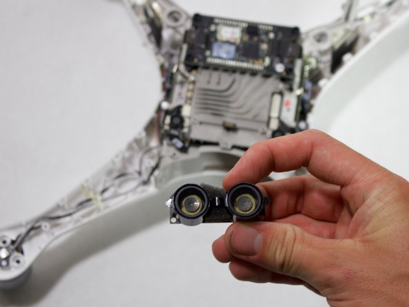
Pry the ribbon cable off the ultrasonic sensor using a plastic opening tool.
-


Cancelar: No complete esta guía.
Una persona más ha completado esta guía.
Equipo

Cal Poly, Team S15-G6, White Fall 2018 Miembro de Cal Poly, Team S15-G6, White Fall 2018
CPSU-WHITE-F18S15G6
4 Miembros
6 Guías creadas