Esta versión puede contener ediciones incorrectas. Cambiar a la última instantánea verificada.
Qué necesitas
-
Este paso está sin traducir. Ayuda a traducirlo
-
Remove the four (9 mm) screws with a PH2 screwdriver.
-
Remove the two (7 mm) located with a PH2 screwdriver.
-
-
Este paso está sin traducir. Ayuda a traducirlo
-
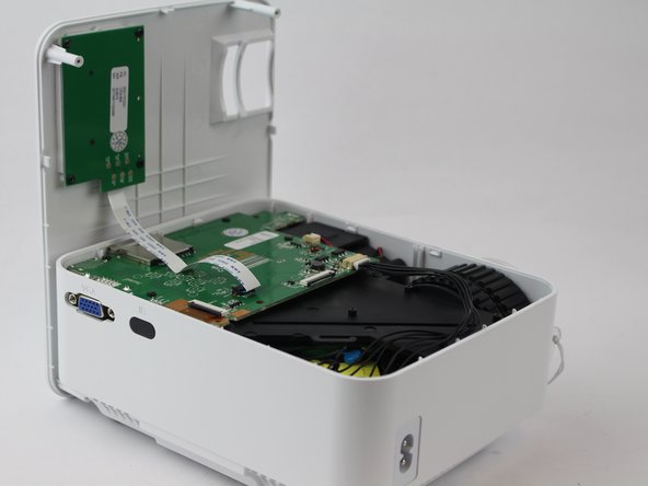
Flip the device over and pry the top off with a plastic opening tool.
-
-
Este paso está sin traducir. Ayuda a traducirlo
-
Remove the ribbon cable connecting the motherboard to the button control board by gently pulling it from its connector.
-
-
Este paso está sin traducir. Ayuda a traducirlo
-
Remove four (6 mm) screws connecting the motherboard using a J0 screwdriver.
-
-
-
Este paso está sin traducir. Ayuda a traducirlo
-
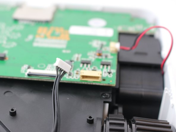
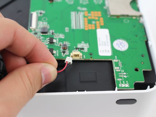
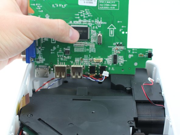
Remove the two cables connected to the motherboard: black power cable and the red/black fan cable.
-
-
Este paso está sin traducir. Ayuda a traducirlo
-
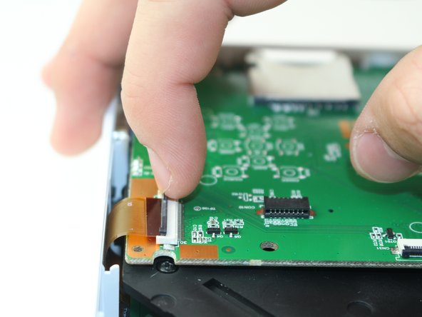
Lift the black latch on the ZIF connector and remove the ribbon cable that attaches the digitizer to the motherboard.
-
-
Este paso está sin traducir. Ayuda a traducirlo
-
Raise motherboard by lifting sideways and then up to avoid the ports.
-
-
Este paso está sin traducir. Ayuda a traducirlo
-
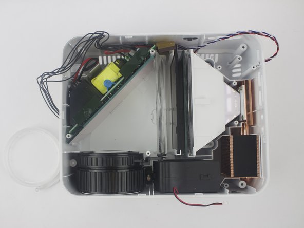
Remove wires attaching the piezoelectric speakers to the motherboard.
-
-
Este paso está sin traducir. Ayuda a traducirlo
-
Remove the five screws securing the black plastic cover with a J0 screwdriver.
-
Lift up and out to remove.
-
-
Este paso está sin traducir. Ayuda a traducirlo
-
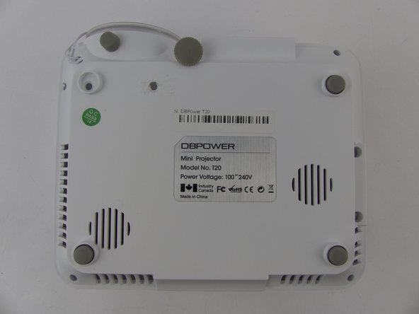
Remove the rubber foot and warranty sticker found underneath the device.
-
-
Este paso está sin traducir. Ayuda a traducirlo
-
Remove the two screws on the bottom of the device with a J0 screwdriver.
-
-
Este paso está sin traducir. Ayuda a traducirlo
-
Remove the focus-adjustment ring from the lens housing.
-


Cancelar: No complete esta guía.
3 personas más completaron esta guía.
Equipo

USF Tampa, Team S16-G2, Boczar Spring 2018 Miembro de USF Tampa, Team S16-G2, Boczar Spring 2018
USFT-BOCZAR-S18S16G2
5 Miembros
5 Guías creadas
3 comentarios
I need to know the same
Trying to put my lens back how to install