Esta versión puede contener ediciones incorrectas. Cambie a la última instantánea verificada.
Qué necesitas
-
Este paso está sin traducir. Ayuda a traducirlo
-
Remove the four (9 mm) screws with a PH2 screwdriver.
-
Remove the two (7 mm) located with a PH2 screwdriver.
-
-
Este paso está sin traducir. Ayuda a traducirlo
-
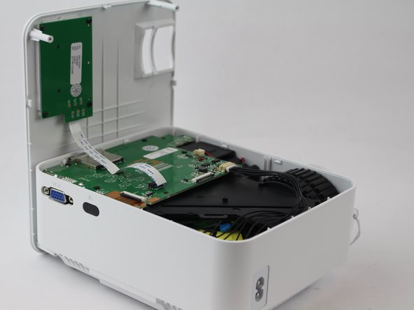
Flip the device over and pry the top off with a plastic opening tool.
-
-
Este paso está sin traducir. Ayuda a traducirlo
-
Remove the ribbon cable connecting the motherboard to the button control board by gently pulling it from its connector.
-
-
-
Este paso está sin traducir. Ayuda a traducirlo
-
Remove four (6 mm) screws connecting the motherboard using a J0 screwdriver.
-
-
Este paso está sin traducir. Ayuda a traducirlo
-
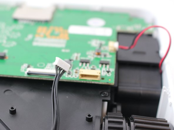
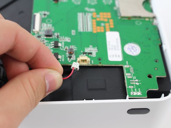
Remove the two cables connected to the motherboard: black power cable and the red/black fan cable.
-
-
Este paso está sin traducir. Ayuda a traducirlo
-
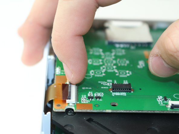
Lift the black latch on the ZIF connector and remove the ribbon cable that attaches the digitizer to the motherboard.
-
-
Este paso está sin traducir. Ayuda a traducirlo
-
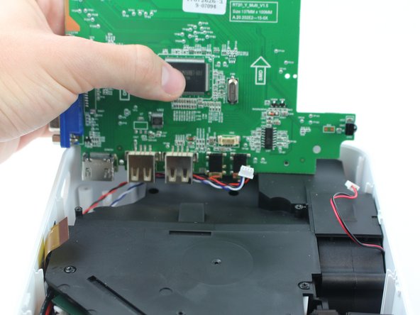
Raise motherboard by lifting sideways and then up to avoid the ports.
-
-
Este paso está sin traducir. Ayuda a traducirlo
-
Remove wires attaching the piezoelectric speakers to the motherboard.
-
-
Este paso está sin traducir. Ayuda a traducirlo
-
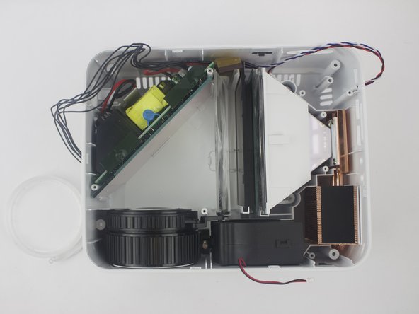
Remove the five screws securing the black plastic cover with a J0 screwdriver.
-
Lift up and out to remove.
-
-
Este paso está sin traducir. Ayuda a traducirlo
-
Remove the two screws attached to the lamp with a J0 screwdriver.
-


Cancelar: No complete esta guía.
4 personas más completaron esta guía.
Equipo

USF Tampa, Team S16-G2, Boczar Spring 2018 Miembro de USF Tampa, Team S16-G2, Boczar Spring 2018
USFT-BOCZAR-S18S16G2
5 Miembros
5 Guías creadas
6 comentarios
The part that is being removed is NOT the LED lamp. My interest is replacing the actual LED lamp that sits behind the plastic part that is being removed. My projector image started to have a tan cast to it near the top left portion of the screen due to overheating. I am just assuming that it is the actual LED that is overheating and need replacing. The article is very good otherwise. Please add where replacement parts can be obtained.
Thank you very much, I appreciate the ability to get a look without having to open it up
Where can i buy the lamp?
Merci pour ce tuto! =) ça ma permis de nettoyer la lentille qui était pleine de poussière!