Saltar al contenido principal

Connecting Cables to the Motherboard

Qué necesitas

  1. Connecting Cables to the Motherboard, Connecting Cables to the Motherboard: paso 1, imagen 1 de 2 Connecting Cables to the Motherboard, Connecting Cables to the Motherboard: paso 1, imagen 2 de 2
    • Red- Optional ATX Connector

    • Orange- CPU Fan 1

    • Yellow- CPU Fan 2

    • Green- Main ATX Connectors

    • Light Blue- GPU

    • Blue- Panel Connectors

    • Pink- USB Connectors

    • Black- HD Audio

  2. Connecting Cables to the Motherboard, Optional ATX Connector: paso 2, imagen 1 de 2 Connecting Cables to the Motherboard, Optional ATX Connector: paso 2, imagen 2 de 2
    • Connect the two separate six-pin segments to six pins each on the 12-pin PCIE port.

  3. Connecting Cables to the Motherboard, CPU Fan 1: paso 3, imagen 1 de 2 Connecting Cables to the Motherboard, CPU Fan 1: paso 3, imagen 2 de 2
    • Connect the four pin segment to the four pin PCEI connector labeled "CPUFAN1."

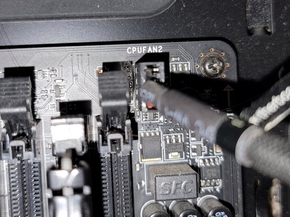
  4. Connecting Cables to the Motherboard, CPU Fan 2: paso 4, imagen 1 de 2 Connecting Cables to the Motherboard, CPU Fan 2: paso 4, imagen 2 de 2
    • Connect the four pin segment to the four pin PCIE port labeled "CPUFAN2."

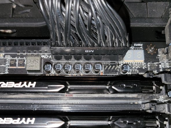
  5. Connecting Cables to the Motherboard, Main ATX Connector: paso 5, imagen 1 de 2 Connecting Cables to the Motherboard, Main ATX Connector: paso 5, imagen 2 de 2
    • Connect the 24 pin segment to the 24 pin PCIE port.

  6. Connecting Cables to the Motherboard, GPU: paso 6, imagen 1 de 2 Connecting Cables to the Motherboard, GPU: paso 6, imagen 2 de 2
    • Connect both of the separate eight pin segments to each of the eight pin PCIE ports on the graphics card.

  7. Connecting Cables to the Motherboard, Panel Connectors (Part 1): paso 7, imagen 1 de 3 Connecting Cables to the Motherboard, Panel Connectors (Part 1): paso 7, imagen 2 de 3 Connecting Cables to the Motherboard, Panel Connectors (Part 1): paso 7, imagen 3 de 3
    • This PCIE port consists of eight pins, two rows of four.

    • Connect the "Power LED+" pin to the pin at the top right corner.

    • Connect the "Power LED-" segment to the pin next to the "Power LED+" segment in the top row.

    • Connect the "Power SW" segment to the two pins on the left side of the top row of pins.

  8. Connecting Cables to the Motherboard, Panel Connectors (Part 2): paso 8, imagen 1 de 3 Connecting Cables to the Motherboard, Panel Connectors (Part 2): paso 8, imagen 2 de 3 Connecting Cables to the Motherboard, Panel Connectors (Part 2): paso 8, imagen 3 de 3
    • Connect the "HDD LED" segment to the two pins on the right side of the bottom row of pins.

    • Connect the "Reset SW" segment to the two pins on the left side of the bottom row of pins.

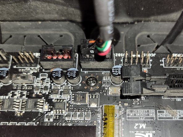
  9. Connecting Cables to the Motherboard, USB Connector: paso 9, imagen 1 de 2 Connecting Cables to the Motherboard, USB Connector: paso 9, imagen 2 de 2
    • Connect the nine pin segment to the nine pin PCIE port.

  10. Connecting Cables to the Motherboard, HD Audio: paso 10, imagen 1 de 2 Connecting Cables to the Motherboard, HD Audio: paso 10, imagen 2 de 2
    • Connect the nine pin segment to the nine pin PCIE port.

Conclusión

To disconnect the cable ties, follow these directions in reverse order.

Grace Parsekian

Miembro Desde 12/05/23

181 Reputación

1 Guía escrita

0 comentarios

Agregar Comentario

Ver Estadísticas:

Ultimas 24 horas: 8

Ultimos 7 días: 96

Ultimos 30 días: 456

Todo El Tiempo: 1,433