Esta versión puede contener ediciones incorrectas. Cambiar a la última instantánea verificada.
Qué necesitas
-
Este paso está sin traducir. Ayuda a traducirlo
-
Use the Phillips #1 Screwdriver to remove the two screws on back side of the device.
-
-
Este paso está sin traducir. Ayuda a traducirlo
-
1. Gently push the top cover of the router away from you.
-
2. Lift it up top cover from the bottom of the router.
-
3. Remove top cover from the device.
-
-
-
Este paso está sin traducir. Ayuda a traducirlo
-
Use the Phillips #1 Screwdriver to remove the three screws on front side of the device.
-
-
Este paso está sin traducir. Ayuda a traducirlo
-
1. Gently lift up inner metal shield from the bottom of the router.
-
2. Remove inner metal shield from the device (see the anchors on the picture).
-
-
Este paso está sin traducir. Ayuda a traducirlo
-
1. Place your fingers on the levers at the two sides of the slot, and push open.
-
2. Firmly pull the release lever away from the module until the module pops up.
-
3. You can then remove the module from the module slot.
-
-
Este paso está sin traducir. Ayuda a traducirlo
-
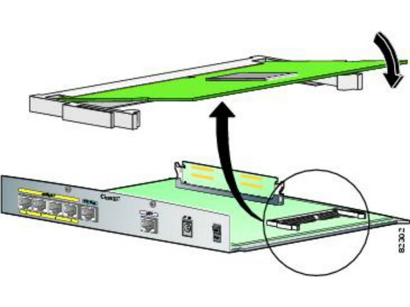
1. Insert the notched edge of the module into the slot at an angle.
-
2. Firmly press down the unnotched edge of the module until you hear a click. The indents must be fully in the notches.
-


Cancelar: No complete esta guía.
Una persona más ha completado esta guía.
Documentos Adjuntos

Equipo
