Saltar al contenido principal

Esta guía ha sufrido modificaciones. Revisa la última versión sin revisar.

Chromo Inc. T2 Motherboard Replacement

Qué necesitas

  1. Chromo Inc. T2 Motherboard Replacement, Removing the Casing: paso 1, imagen 1 de 3 Chromo Inc. T2 Motherboard Replacement, Removing the Casing: paso 1, imagen 2 de 3 Chromo Inc. T2 Motherboard Replacement, Removing the Casing: paso 1, imagen 3 de 3
    • Place your Plastic Opening Tool between the screen and the case. Slowly move it around the casing while prying in a downward motion to undo the hinges holding the two together and separate the two parts.

  2. Chromo Inc. T2 Motherboard Replacement, Turn it around: paso 2, imagen 1 de 1
    • After separating the case and screen, turn your screen face down so you can see the internal parts!

  3. Chromo Inc. T2 Motherboard Replacement, Disconnecting Flex Cables: paso 3, imagen 1 de 2 Chromo Inc. T2 Motherboard Replacement, Disconnecting Flex Cables: paso 3, imagen 2 de 2
    • Peel back the tape holding the big flex cable in place.

    • Using your plastic opening tool, gently push back the gray connector to free the flex cables and then pull them out.

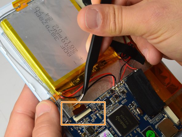
  4. Chromo Inc. T2 Motherboard Replacement, Disconnecting the Camera: paso 4, imagen 1 de 2 Chromo Inc. T2 Motherboard Replacement, Disconnecting the Camera: paso 4, imagen 2 de 2
    • Using the small plastic opening tool, gently push the gray connector back to unlock the flex cable.

    • Using a pair of tweezers, gently grasp the flex cable and disconnect it from the connector.

  5. Chromo Inc. T2 Motherboard Replacement: paso 5, imagen 1 de 2 Chromo Inc. T2 Motherboard Replacement: paso 5, imagen 2 de 2
    • Using a Phillips #00 Precision Screwdriver, remove the three 3mm screws holding the motherboard.

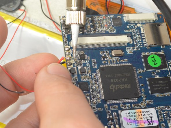
  6. Chromo Inc. T2 Motherboard Replacement: paso 6, imagen 1 de 3 Chromo Inc. T2 Motherboard Replacement: paso 6, imagen 2 de 3 Chromo Inc. T2 Motherboard Replacement: paso 6, imagen 3 de 3
    • Using your soldering iron, desolder the six wires on the side of the logic board.

    • Note: Remember where these wires go as re-connecting them incorrectly can lead to damaging the device!

    • Soldering Iron gets very hot, take care to not touch anywhere on the soldering iron except for the handle!

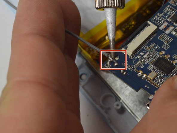
  7. Chromo Inc. T2 Motherboard Replacement: paso 7, imagen 1 de 2 Chromo Inc. T2 Motherboard Replacement: paso 7, imagen 2 de 2
    • Using your soldering Iron, desolder the grounding cable on the motherboard.

    • Soldering Iron gets very hot, take care to not touch anywhere on the soldering iron except for the handle!

  8. Chromo Inc. T2 Motherboard Replacement: paso 8, imagen 1 de 1
    • Your motherboard is now ready for replacement!

Conclusión

To reassemble your device, follow these instructions in reverse order.

Ismael DeLuna

Miembro Desde 01/21/15

637 Reputación

5 Guías creadas

Equipo

USF Tampa, Team 15-1, Watkins Winter 2015 Miembro de USF Tampa, Team 15-1, Watkins Winter 2015

USFT-WATKINS-W15S15G1

4 Miembros

6 Guías creadas

0 comentarios

Agregar Comentario

Ver Estadísticas:

Ultimas 24 horas: 0

Ultimos 7 días: 0

Ultimos 30 días: 1

Todo El Tiempo: 633