Esta versión puede contener ediciones incorrectas. Cambie a la última instantánea verificada.
Qué necesitas
-
Este paso está sin traducir. Ayuda a traducirlo
-
Remove eight 1.8 mm screws from the left and right sides of the camera using a Phillips #00 screwdriver
-
-
Este paso está sin traducir. Ayuda a traducirlo
-
Remove the four 3.7 mm screws from the bottom of the camera using a Phillips #00 screwdriver.
-
-
Este paso está sin traducir. Ayuda a traducirlo
-
Separate the front case from the body of the camera.
-
-
Este paso está sin traducir. Ayuda a traducirlo
-
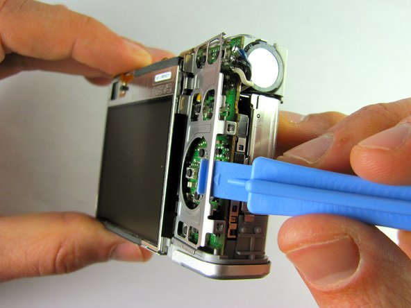
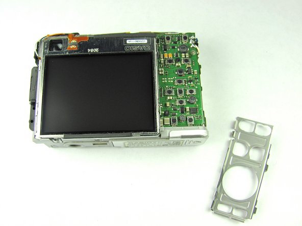
Remove the metal grating located to the right of the LCD screen by inserting the plastic opening tool under the grating and pulling up.
-
-
Este paso está sin traducir. Ayuda a traducirlo
-
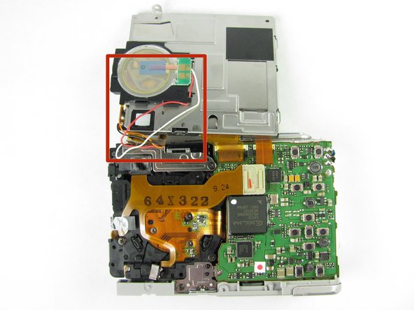
Before removing the side metal bracket, first remove the attached strap knob by twisting it off.
-
Then, remove the side metal bracket by inserting the plastic opening tool under the bracket and pulling up.
-
-
Este paso está sin traducir. Ayuda a traducirlo
-
Using the plastic opening tool, pry up the LCD screen starting at one of the corners. Insert the tool under one of the corners and lift up.
-
-
Este paso está sin traducir. Ayuda a traducirlo
-
Remove the orange ribbon cable by grabbing the white tab with your fingers and pulling gently.
-
-
Este paso está sin traducir. Ayuda a traducirlo
-
Remove the two 1.7 mm screws from the motherboard using a Phillips #00 screwdriver.
-
-
Este paso está sin traducir. Ayuda a traducirlo
-
Using the iFixit plastic opening tool, pry the battery case clamps on the front of the camera so that the bottom will come loose.
-
-
Este paso está sin traducir. Ayuda a traducirlo
-
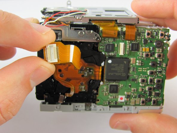
Detach the inner orange ribbon cable that connects the motherboard to the lens by inserting the iFixit plastic opening tool under the tab and lifting up.
-


Cancelar: No complete esta guía.
2 personas más completaron esta guía.
Equipo

Cal Poly, Team 9-45, Regan Spring 2012 Miembro de Cal Poly, Team 9-45, Regan Spring 2012
CPSU-REGAN-S12S9G45
7 Miembros
12 Guías creadas
Un comentario
I veganlover loved this guide! Although it wasn’t vegan enough