Esta versión puede contener ediciones incorrectas. Cambiar a la última instantánea verificada.
Qué necesitas
-
Este paso está sin traducir. Ayuda a traducirlo
-
Remove the three 3.8 mm screws from the underside of the camera.
-
-
Este paso está sin traducir. Ayuda a traducirlo
-
Remove the 3.2 mm screw from the right side of the camera.
-
Remove the 2.2 mm screw from the right side of the camera.
-
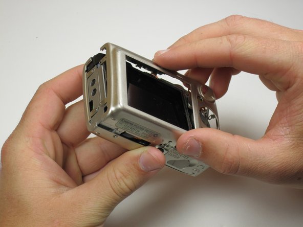
Lift the side panel off.
-
Remove the 1.8 mm screw from underneath the side panel.
-
-
Este paso está sin traducir. Ayuda a traducirlo
-
Remove the two 2.2 mm screws from the left side of the camera.
-
Lift the plate from the camera.
-
-
-
Este paso está sin traducir. Ayuda a traducirlo
-
Gently lift the rear of the case to remove it from the camera.
-
-
Este paso está sin traducir. Ayuda a traducirlo
-
Peel the navigation buttons from the button panel and set them aside.
-
To free the LCD display, remove the 2.9 mm screw in the top left corner.
-
Rotate the screen clockwise until it lifts away from the camera.
-
-
Este paso está sin traducir. Ayuda a traducirlo
-
To unplug the ribbon cables, pull them straight out of their plugs. Do this gently to avoid damaging the connections.
-
After disconnecting both cables, pull the screen away from the camera to remove it.
-
-
Este paso está sin traducir. Ayuda a traducirlo
-
Remove the two 3.4 mm screws still holding the button contact panel onto the camera.
-
Using the spudger, disconnect the ribbon cable attaching the button contact panel to the motherboard.
-
Gently pull the button contact panel away from the motherboard.
-
-
Este paso está sin traducir. Ayuda a traducirlo
-
Underneath the button contact panel, you will find a large connector.
-
Using the spudger as leverage, unplug the connector, and pull it away from the motherboard.
-
-
Este paso está sin traducir. Ayuda a traducirlo
-
The last ribbon is held in place by the blue flap. Insert the spudger under the blue flap.
-
Using the spudger as leverage, flip the blue flap up, which will unlock the ribbon.
-
Place the spudger into the hole in the ribbon, and pull the ribbon away from the connector.
-
-
Este paso está sin traducir. Ayuda a traducirlo
-
Remove the motherboard by pulling it out with either tweezers or the spudger.
-


Equipo

Cal Poly, Team 18-23, Garner Spring 2011 Miembro de Cal Poly, Team 18-23, Garner Spring 2011
CPSU-GARNER-S11S18G23
5 Miembros
7 Guías creadas