Esta versión puede contener ediciones incorrectas. Cambiar a la última instantánea verificada.
Qué necesitas
-
Este paso está sin traducir. Ayuda a traducirlo
-
Remove the two 4.8 mm black screws above the lens on the front of the camera.
-
-
Este paso está sin traducir. Ayuda a traducirlo
-
Remove the 4.3 mm black screw under the lens ring, and the 4.8 mm black screw under the camera.
-
-
Este paso está sin traducir. Ayuda a traducirlo
-
Remove the 4.8 mm black screw on the left side of the camera.
-
-
Este paso está sin traducir. Ayuda a traducirlo
-
Remove the front panel by lifting it away from the camera's body.
-
-
-
Este paso está sin traducir. Ayuda a traducirlo
-
Remove the plastic remote control socket cap by pulling it straight out.
-
-
Este paso está sin traducir. Ayuda a traducirlo
-
Slide the panel toward the bottom of the camera to remove.
-
-
Este paso está sin traducir. Ayuda a traducirlo
-
Remove the single 4.8 silver screw from the control socket.
-
-
Este paso está sin traducir. Ayuda a traducirlo
-
Desolder connections to replace the remote control socket.
-
-
Este paso está sin traducir. Ayuda a traducirlo
-
Remove one 4.8 mm silver screw securing Remote Control Socket to camera.
-
-
Este paso está sin traducir. Ayuda a traducirlo
-
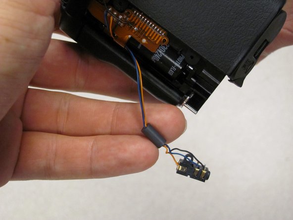
Remote Control Socket is now secured by 3 wires.
-
Desolder connections to replace Remote Control Socket.
-


Cancelar: No complete esta guía.
2 personas más completaron esta guía.
Equipo

Cal Poly, Team 8-8, Regan Spring 2011 Miembro de Cal Poly, Team 8-8, Regan Spring 2011
CPSU-REGAN-S11S8G8
5 Miembros
22 Guías creadas