Esta versión puede contener ediciones incorrectas. Cambie a la última instantánea verificada.
Qué necesitas
-
Este paso está sin traducir. Ayuda a traducirlo
-
Turn computer over.
-
Remove battery expansion cover and battery.
-
-
Este paso está sin traducir. Ayuda a traducirlo
-
With monitor hinge at the bottom, remove the two top center screws.
-
-
Este paso está sin traducir. Ayuda a traducirlo
-
Open computer kickstands.
-
Remove screws underneath each kickstand.
-
-
-
Este paso está sin traducir. Ayuda a traducirlo
-
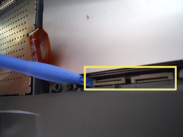
Lift the white ribbon clamps securing the keyboard ribbon cables to the motherboard. You can do this using a plastic opening tool.
-
Removing both ribbon cables from the motherboard will leave the clamps like so.
-
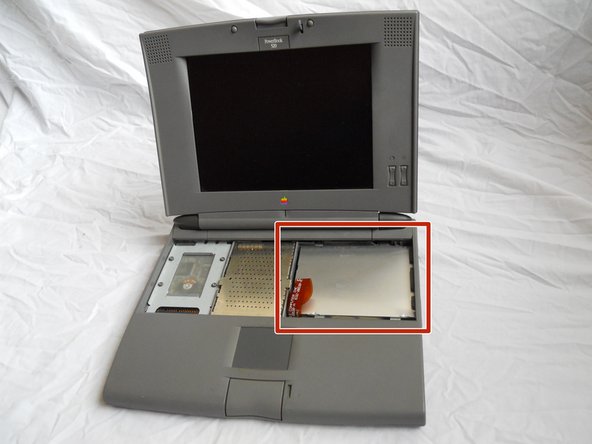
From here you can access the logic board, hard drive, and floppy drive.
-
-
Este paso está sin traducir. Ayuda a traducirlo
-
Open the panel on back of the device. Remove 2 T8 torque screws.
-
-
Este paso está sin traducir. Ayuda a traducirlo
-
Remove the 2 T8 Torx Screws securing the logic board protection plate from the midsection of the logic board protection plate. Remove the T8 Torx Screw from the back of the plate, underneath the hinge.
-
-
Este paso está sin traducir. Ayuda a traducirlo
-
Using a plastic spudger, gently pry up the uppermost board fixture. This is the Memory (RAM).
-
-
Este paso está sin traducir. Ayuda a traducirlo
-
Once the old Memory board is removed, replace it with the new Memory board.
-


Cancelar: No complete esta guía.
2 personas más completaron esta guía.
Equipo

Cal Poly, Team 20-66, Walters Spring 2011 Miembro de Cal Poly, Team 20-66, Walters Spring 2011
CPSU-WALTERS-S11S20G66
4 Miembros
3 Guías creadas