Esta versión puede contener ediciones incorrectas. Cambiar a la última instantánea verificada.
Qué necesitas
-
Este paso está sin traducir. Ayuda a traducirlo
-
Place the Cinema Display so that it is lying on its face and the feet are pointed away from you.
-
Remove the three screws (9.52 x 4.43mm) that connect the back foot to the hinge using the Hex Key.
-
Remove the back foot from the hinge mount by grabbing the foot and pulling upwards.
-
-
Este paso está sin traducir. Ayuda a traducirlo
-
Remove the eighteen (5.25 x 4.43 mm) screws around the edge of the backplate using the Hex key.
-
Disconnect the small white connector leading to the display's Power button.
-
Gently lift the backplate off of the display. Completely remove the backplate and set it aside.
-
-
Este paso está sin traducir. Ayuda a traducirlo
-
Use a Phillips #2 screwdriver to remove the four (9.52 x 3.43 mm) screws on the outer rim of the metal cover.
-
Next, remove the four cover (11.91 x 2.89 mm) screws located at the corners of the metal cover using the Phillips #2 screwdriver.
-
-
Este paso está sin traducir. Ayuda a traducirlo
-
Unplug the large brown plug in the center-right, that connects the control board to the rest of the display.
-
Unplug the blue and gray plug on the right side of the control board. Repeat with the left side.
-
-
Este paso está sin traducir. Ayuda a traducirlo
-
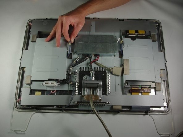
Gently lift the large metal cover which spans across the back of the whole display.
-
-
Este paso está sin traducir. Ayuda a traducirlo
-
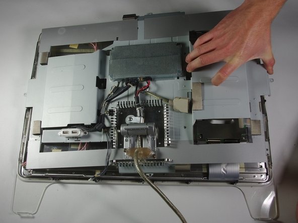
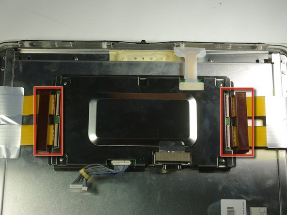
Carefully remove the two tape plugs on either side of the control board using a spudger.
-
-
Este paso está sin traducir. Ayuda a traducirlo
-
Pull the previously removed tape out from the metal box with your hand.
-
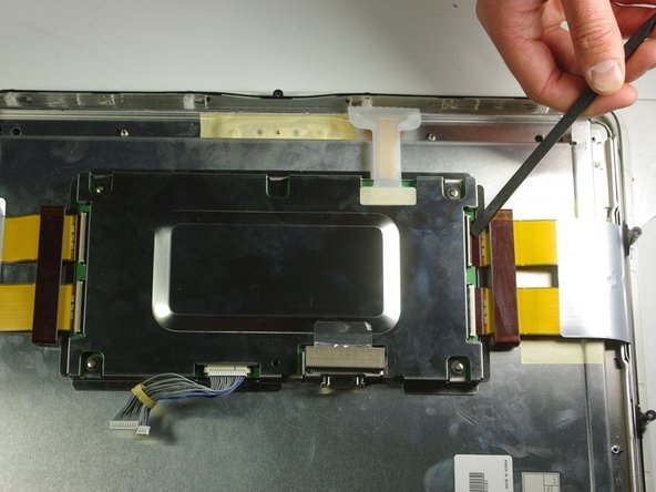
Peel back the white plastic cover located on the tape plug and unplug the tape plug on the right side of the unit using the spudger.
-
-
Este paso está sin traducir. Ayuda a traducirlo
-
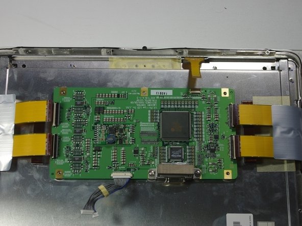
Unscrew the four screws (4.79x2.33mm) on the metal box using the Phillips #2 screwdriver.
-
Lift the metal cover off to reveal a circuit board.
-
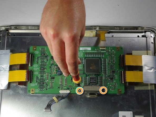
Remove the two terminal screws (4.79x2.34mm) using the Phillips #2 screwdriver.
-
-
Este paso está sin traducir. Ayuda a traducirlo
-
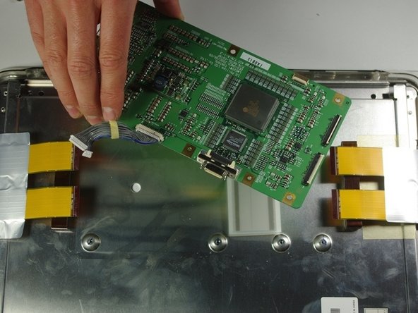
Remove the terminal cover.
-
Remove the circuit board from the right side of the unit by gently lifting it out.
-


Cancelar: No complete esta guía.
Una persona más ha completado esta guía.
Equipo

Cal Poly, Team 10-41, Forte Spring 2011 Miembro de Cal Poly, Team 10-41, Forte Spring 2011
CPSU-FORTE-S11S10G41
5 Miembros
12 Guías creadas