Saltar al contenido principal

Esta versión puede contener ediciones incorrectas. Cambiar a la última instantánea verificada.

Qué necesitas

  1. Este paso está sin traducir. Ayuda a traducirlo

    : paso 1, imagen 1 de 1
    • Welcome to the Alienware M11xR3 disassembly. Below, I will describe the necessary tools and steps to disassemble the Alienware M11xR3. This disassembly applies to all M11x, including the R1, R2, and R3.

    • Required tools:

    • 1x Phillips #1 and #00 Screwdriver

    • 1x Flathead Screwdriver

    • 1x Small Needle Nose Pliers or Tweezers

    • 1x Thermal Paste and Finger Stalls Optional: Small water balloons (to spread thermal paste without getting dirty)

    • 1x Anti-Static Mat

    • I highly recommended reading about static electricity and how it can damage electronic components.

  2. Este paso está sin traducir. Ayuda a traducirlo

    : paso 2, imagen 1 de 2 : paso 2, imagen 2 de 2
    • Gently flip over the laptop so that the bottom side is facing up.

    • Use a Phillips #1 screwdriver to remove the 8 screws securing the base-plate.

  3. Este paso está sin traducir. Ayuda a traducirlo

    : paso 3, imagen 1 de 1
    • Lift the bottom cover and remove it.

  4. Este paso está sin traducir. Ayuda a traducirlo

    : paso 4, imagen 1 de 3 : paso 4, imagen 2 de 3 : paso 4, imagen 3 de 3
    • Remove the battery cable on the plate by pulling vertically.

    • Unscrew and remove the screws retaining the battery.

  5. Este paso está sin traducir. Ayuda a traducirlo

    : paso 5, imagen 1 de 1
    • Remove the battery.

  6. Este paso está sin traducir. Ayuda a traducirlo

    : paso 6, imagen 1 de 2 : paso 6, imagen 2 de 2
    • Remove the hard drive mounting bracket by removing the three screws with the Phillips #1 screwdriver.

    • Pull out the hard drive by lifting up on the black tab.

  7. Este paso está sin traducir. Ayuda a traducirlo

    : paso 7, imagen 1 de 3 : paso 7, imagen 2 de 3 : paso 7, imagen 3 de 3
    • In order to remove the hard drive from the mounting bracket, remove the four screws at each corner with the Phillips #1 screwdriver.

    • When installing a new hard drive, never forget to remove the SATA adapter before installation.

  8. Este paso está sin traducir. Ayuda a traducirlo

    : paso 8, imagen 1 de 3 : paso 8, imagen 2 de 3 : paso 8, imagen 3 de 3
    • Pull the tabs away from RAM.

    • Carefully pull the RAM module to remove.

    • Depending on the configuration that you have on your Alienware, there may be another RAM module.

    • If you want to upgrade your RAM please read the manual about which modules are compatible. Here are the RAM specs:

    • Number of Sockets: 2

    • Max memory: 16384 MB (16GB)

    • Memory Comments: PC3-10600 1333Mhz DDR3 SDRAM SO-DIMM 204-pin

  9. Este paso está sin traducir. Ayuda a traducirlo

    : paso 9, imagen 1 de 3 : paso 9, imagen 2 de 3 : paso 9, imagen 3 de 3
    • Depending on your Alienware configuration, it can have up to 3 aerial cables.

    • Remove the aerial cables vertically with Tweezers or Small Needle Nose Pliers.

    • Once the aerial cables are removed, extract the screws.

    • Remove the WLAN card.

    • On USA models, a WWAN card may be located near the WLAN card. Use the same process to remove it.

  10. Este paso está sin traducir. Ayuda a traducirlo

    : paso 10, imagen 1 de 3 : paso 10, imagen 2 de 3 : paso 10, imagen 3 de 3
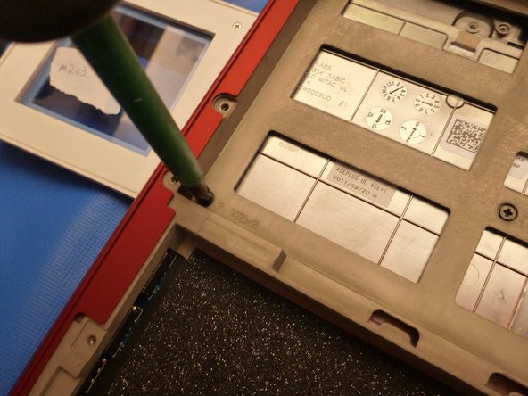
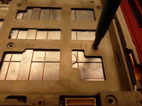
    • Remove the chassis screws using a Phillips #1 screwdriver.

    • Remove the keyboard screws using a Phillips #1 screwdriver.

  11. Este paso está sin traducir. Ayuda a traducirlo

    : paso 11, imagen 1 de 3 : paso 11, imagen 2 de 3 : paso 11, imagen 3 de 3
    • Remove the chassis screws.

  12. Este paso está sin traducir. Ayuda a traducirlo

    : paso 12, imagen 1 de 2 : paso 12, imagen 2 de 2
    • Remove the bottom chassis screws.

  13. Este paso está sin traducir. Ayuda a traducirlo

    : paso 13, imagen 1 de 2 : paso 13, imagen 2 de 2
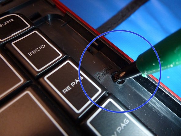
    • The screw marked with a yellow circle is near the hard drive bay.

  14. Este paso está sin traducir. Ayuda a traducirlo

    : paso 14, imagen 1 de 2 : paso 14, imagen 2 de 2
    • Remove the screws from the keyboard.

  15. Este paso está sin traducir. Ayuda a traducirlo

    : paso 15, imagen 1 de 3 : paso 15, imagen 2 de 3 : paso 15, imagen 3 de 3
    • Use a small flat screwdriver to carefully pry the cover from the chassis.

    • Next, use your finger as a lever to extract the cover. The cover has tabs that attach it to the chassis.

    • In the next step, I'll show you tab locations.

  16. Este paso está sin traducir. Ayuda a traducirlo

    : paso 16, imagen 1 de 3 : paso 16, imagen 2 de 3 : paso 16, imagen 3 de 3
    • Clamping tabs

  17. Este paso está sin traducir. Ayuda a traducirlo

    : paso 17, imagen 1 de 2 : paso 17, imagen 2 de 2
    • Remove the two screws to release the keyboard.

    • Wait for the next step to remove the keyboard; there are bus data cables underneath the keyboard that must be removed first.

  18. Este paso está sin traducir. Ayuda a traducirlo

    : paso 18, imagen 1 de 3 : paso 18, imagen 2 de 3 : paso 18, imagen 3 de 3
    • There are 2 bus data cables.

    • The thin orange cable is the RGB led keyboard retro illumination.

    • Lift the tab to a vertical position to free the bus cable as shown.

  19. Este paso está sin traducir. Ayuda a traducirlo

    : paso 19, imagen 1 de 3 : paso 19, imagen 2 de 3 : paso 19, imagen 3 de 3
    • Free the keyboard bus data cable as you did for the RGB bus data cable.

    • Remove the keyboard to replace it; it has pressure points like the previous cover.

    • If the keyboard fails, the best option is to replace it for a new one.

  20. Este paso está sin traducir. Ayuda a traducirlo

    : paso 20, imagen 1 de 3 : paso 20, imagen 2 de 3 : paso 20, imagen 3 de 3
    • Continue taking out the chassis by unscrewing the 3 shown screws.

    • First one to the left of the RGB bus data cable.

    • Second one at bottom near the touchpad.

    • Third one on the right edge of the laptop.

  21. Este paso está sin traducir. Ayuda a traducirlo

    : paso 21, imagen 1 de 3 : paso 21, imagen 2 de 3 : paso 21, imagen 3 de 3
    • Lift the tab to disconnect the touchpad data bus cable.

  22. Este paso está sin traducir. Ayuda a traducirlo

    : paso 22, imagen 1 de 3 : paso 22, imagen 2 de 3 : paso 22, imagen 3 de 3
    • Extract the bus cable with needle nose pliers by lifting the tab and pulling it away.

    • If your computer doesn't power on, then check to make sure this cable is plugged in.

    • Always lift tabs vertically to free cables.

  23. Este paso está sin traducir. Ayuda a traducirlo

    : paso 23, imagen 1 de 3 : paso 23, imagen 2 de 3 : paso 23, imagen 3 de 3
    • Lift the case with your fingers, as shown in the pictures.

    • Don't remove the case yet. There is another cable on the upper left corner that must be removed to fully remove the case.

  24. Este paso está sin traducir. Ayuda a traducirlo

    : paso 24, imagen 1 de 2 : paso 24, imagen 2 de 2
    • This is the cable that I mentioned in the previous step.

    • Pull the cable out to the right to remove it.

  25. Este paso está sin traducir. Ayuda a traducirlo

    : paso 25, imagen 1 de 2 : paso 25, imagen 2 de 2
    • Here's a top and bottom view of the board with the power on switch and LED status.

  26. Este paso está sin traducir. Ayuda a traducirlo

    : paso 26, imagen 1 de 1
    • And here's a bottom view of the touchpad.

  27. Este paso está sin traducir. Ayuda a traducirlo

    : paso 27, imagen 1 de 2 : paso 27, imagen 2 de 2
    • Remove the shown screw.

    • Pull the cable off.

  28. Este paso está sin traducir. Ayuda a traducirlo

    : paso 28, imagen 1 de 1
    • This is the BIOS battery for internal configuration and clock. If you have problems with it, remove it by disconnecting it from the motherboard.

  29. Este paso está sin traducir. Ayuda a traducirlo

    : paso 29, imagen 1 de 3 : paso 29, imagen 2 de 3 : paso 29, imagen 3 de 3
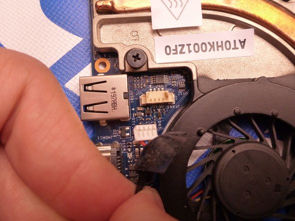
    • Pull the speakers connector towards you and away from the I/O board, marked by a yellow square.

    • Remove the 3 screws and lift as you see in the picture

    • Move the board a little to the left while lifting to prevent damaging the two attached USB 3.0 ports.

  30. Este paso está sin traducir. Ayuda a traducirlo

    : paso 30, imagen 1 de 3 : paso 30, imagen 2 de 3 : paso 30, imagen 3 de 3
    • Remove the display connector by pulling vertically.

    • Lift using the plastic tab. See the image provided in this step.

  31. Este paso está sin traducir. Ayuda a traducirlo

    : paso 31, imagen 1 de 3 : paso 31, imagen 2 de 3 : paso 31, imagen 3 de 3
    • Unscrew the screws in the correct order by using the numbers near the holes.

    • Make sure you are holding the monitor while unscrewing to prevent dropping and damaging the screen.

    • After that, you must see the next step to remove the WLAN aerials.

  32. Este paso está sin traducir. Ayuda a traducirlo

    : paso 32, imagen 1 de 2 : paso 32, imagen 2 de 2
    • The WLAN cable is the same as in step 9.

    • Pass the cable from the bottom of the laptop through the hole carefully.

    • Remember, depending on your Alienware configuration you may have 2 or 3 aerials. USA customers may also have the WWAN aerials

  33. Este paso está sin traducir. Ayuda a traducirlo

    : paso 33, imagen 1 de 3 : paso 33, imagen 2 de 3 : paso 33, imagen 3 de 3
    • Remove the four screws, marked by red circles, to remove the motherboard.

    • Now lift the motherboard slowly up while moving it to the right. Removing it this way prevents damage to your ports.

    • As you see in the picture, the I/O board and screen connector wasn't here. They must be disconnected before removing the motherboard, not like the bluetooth board or coin-cell battery.

  34. Este paso está sin traducir. Ayuda a traducirlo

    : paso 34, imagen 1 de 2 : paso 34, imagen 2 de 2
    • Disconnect the vent connector.

    • You must disconnect it to remove the heatsink.

    • To replace the vent, it is not necessary to remove the heatsink. You must do this step and in the next step I have marked in green the 3 screws that you need to remove.

    • To maintain good ventilation, clean the vent with compressed air.

  35. Este paso está sin traducir. Ayuda a traducirlo

    : paso 35, imagen 1 de 3 : paso 35, imagen 2 de 3 : paso 35, imagen 3 de 3
    • If this is your first time applying thermal paste, I recommend using a quality thermal paste brand like Arctic Silver and reading a guide here on iFixit.

    • With the motherboard out, turn it upside down on a static free surface.

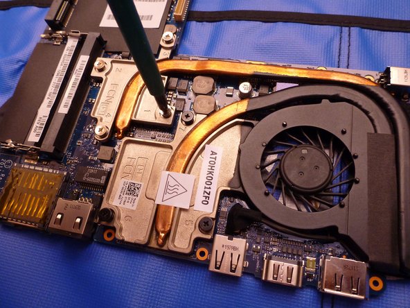
    • To remove the heatsink and replace thermal paste, remove the screws in the correct order (marked with a number on the heatsink).

    • Clean old thermal paste with isopropyl alcohol. Ensure that after applying thermal paste it doesn't leak onto the motherboard (if it's on the green square, it's fine).

    • When putting the heat sink back on, try to have the screw holes align on your first try. This is to maintain an even spread of the thermal paste.

    • Rescrew in the correct order (refer to the numbers on the heat sink).

    • Tighten each screw one at a time to end up with good heat dissipation.

Linea de Meta

7 personas más completaron esta guía.

AdrianP

Miembro Desde 09/05/13

442 Reputación

1 Guía escrita

2 comentarios

I needed to modify it so i t would work for my M11X R1

but after all, pretty goosd tutorial.

Szymon PlayZGameZ - Contestar

Awesomely detailed, thank you :)

fraser - Contestar

Agregar Comentario

Ver Estadísticas:

Ultimas 24 horas: 1

Ultimos 7 días: 10

Ultimos 30 días: 57

Todo El Tiempo: 24,165