Esta versión puede contener ediciones incorrectas. Cambiar a la última instantánea verificada.
Qué necesitas
-
Este paso está sin traducir. Ayuda a traducirlo
-
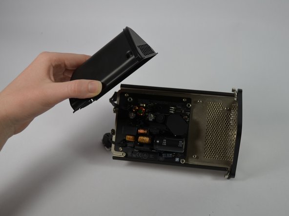
Using a metal spudger, gently pry the cover off the bottom of the device.
-
-
Este paso está sin traducir. Ayuda a traducirlo
-
To detach the small clips from the connectors, place the flat end of the plastic spudger underneath the clip and gently lever it away from the center of the device.
-
To detach the large clip from its connector, place the flat end of the spudger on the clip and lever it upward out of the connector.
-
-
Este paso está sin traducir. Ayuda a traducirlo
-
Using two fingers, pinch the power supply wire and gently lift it upward. Move it away from the metal plate.
-
Next, unscrew the four 3.3mm T8 Torx screws and remove the metal plate.
-
-
-
Este paso está sin traducir. Ayuda a traducirlo
-
Remove the T8 Torx screwdriver head and replace it with the 60 mm extension; then, add the T9 Torx head.
-
Loosen, but do not remove the two screws at the bottom of the 1.2-inch wide gap in the middle of the internal structure.
-
-
Este paso está sin traducir. Ayuda a traducirlo
-
Using only your fingers, gently compress the internal structure and pull evenly upward to remove it from the white case.
-
-
Este paso está sin traducir. Ayuda a traducirlo
-
Rotate the internal structure so that the white ports are facing away from you.
-
Three 8.2mm T8 Torx screws connect the fan to the internal structure. Unscrew all three.
-
-
Este paso está sin traducir. Ayuda a traducirlo
-
Remove the four 10.35 mm Torx T8 screws on the black plastic shell.
-


Cancelar: No complete esta guía.
13 personas más completaron esta guía.
Equipo

Cal Poly, Team 4-26, Amido Fall 2013 Miembro de Cal Poly, Team 4-26, Amido Fall 2013
CPSU-AMIDO-F13S4G26
5 Miembros
18 Guías creadas
4 comentarios
When removing the fan pay attention to the cable. It is glued down with sticky tape and is routed beneath the rubber seal that mates against the case. You may want to remove the power supply cover first since the cable for the fan is routed beneath its cover. But once the power supply fasteners are removed the power supply is dangling from its cables so be careful to relieve the strain.
Splendid! It worked! I'm so happy. The old fan did really have some slackness and the new one makes no sound. Thanks for describing how to change the fan.
I replaced the power supply but the router still does turn on, any advice?