Esta versión puede contener ediciones incorrectas. Cambiar a la última instantánea verificada.
Qué necesitas
-
Este paso está sin traducir. Ayuda a traducirlo
-
Flip your Chromebook over so the bottom is facing up.
-
-
Este paso está sin traducir. Ayuda a traducirlo
-
Remove the 6 mm Phillips #00 screw that holds the back cover on.
-
Carefully lift the cover off.
-
Place the cover and screw safely to the side for now.
-
-
Este paso está sin traducir. Ayuda a traducirlo
-
Using the spudger or your finger, slide the battery release slider and hold in place as shown.
-
-
Este paso está sin traducir. Ayuda a traducirlo
-
Remove the two 3 mm Phillips #00 screws located on the WiFi card.
-
Pop the wires off the WiFi card.
-
Tilt the WiFi card up and remove it by pulling.
-
-
Este paso está sin traducir. Ayuda a traducirlo
-
Remove the fifteen 6 mm Phillips #00 screws holding on the plastic backing panel.
-
Remove the five 3 mm Phillips #00 screws holding on the plastic backing panel.
-
-
Este paso está sin traducir. Ayuda a traducirlo
-
Use the opening tool to pull the tabs back for the ribbon cable of the Solid State Drive.
-
Gently pull the ribbon cable out.
-
Remove the Solid State Drive.
-
-
-
Este paso está sin traducir. Ayuda a traducirlo
-
Use the opening tool to pull the tabs back for the ribbon cable located under the RAM board.
-
Gently pull the ribbon cable out from under the RAM board using the angled tweezers.
-
-
Este paso está sin traducir. Ayuda a traducirlo
-
Use the opening tool to pry apart the seam around the outer perimeter of the back casing.
-
Pry apart the back casing from the keyboard housing.
-
-
Este paso está sin traducir. Ayuda a traducirlo
-
Use the opening tool to pull back the tabs on the ribbon cable still connecting the keyboard and the back panel.
-
Use the angled tweezers to gently remove the ribbon cable.
-
-
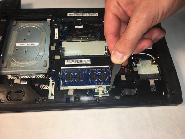
Este paso está sin traducir. Ayuda a traducirlo
-
Using the opening tool, gently pull out the connector that connects the left speaker to the motherboard.
-
Lift, but do not completely remove the speakers. They are still attached by wire.
-
-
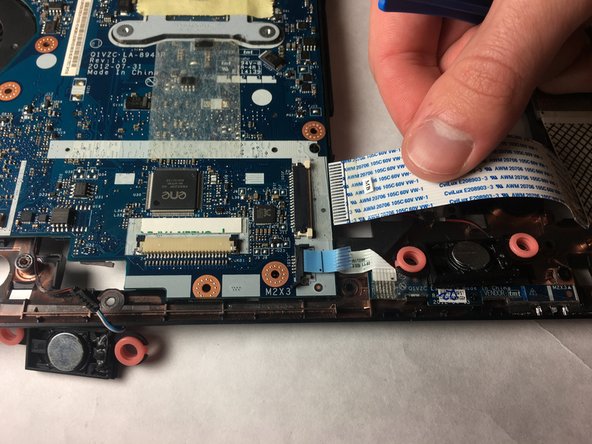
Este paso está sin traducir. Ayuda a traducirlo
-
Using the opening tool, gently pull the two connector flanges holding the large ribbon cable.
-
Gently pull the large ribbon cable to disconnect it.
-
-
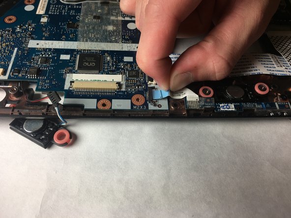
Este paso está sin traducir. Ayuda a traducirlo
-
Use an opening tool to remove the head of the last connected ribbon cable.
-
With your hand, grasp the pull tab and disconnect the ribbon cable.
-
-
Este paso está sin traducir. Ayuda a traducirlo
-
Using the opening tool, gently pull the connector flange connecting the small wires.
-
Gently pull the black connector from the cream-colored connector to disconnect the wires.
-
-
Este paso está sin traducir. Ayuda a traducirlo
-
Remove the 3mm #00 Phillips screw near the bottom of the blue board.
-
-
Este paso está sin traducir. Ayuda a traducirlo
-
Using the opening tool, gently pry the main circuit board out of the casing.
-
Gently tilt the main circuit board up.
-
Place the circuit board to the side.
-
-
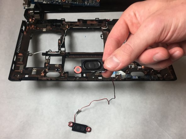
Este paso está sin traducir. Ayuda a traducirlo
-
Remove the black tape over the wire, holding it in.
-
Remove the wire from under the hooks keeping it in place.
-
The speakers and wires are now ready to be removed, and new ones installed.
-


Equipo

IUPUI, Team S1-G6, Harley Fall 2018 Miembro de IUPUI, Team S1-G6, Harley Fall 2018
IUPUI-HARLEY-F18S1G6
3 Miembros
4 Guías creadas