Qué necesitas
-
Este paso está sin traducir. Ayuda a traducirlo
-
Turn the laptop upside down.
-
Locate the battery.
-
Unlock the battery by shifting the 'lock' slide to the 'unlock' position on the underside and back of the system.
-
Hold the release on the right side and remove the battery out carefully.
-
-
Este paso está sin traducir. Ayuda a traducirlo
-
Remove the four screws from the heat sink panel with the phillips screwdriver.
-
Unscrew the two screws from the memory panel with the phillips screwdriver.
-
Remove both panels and set aside.
-
-
Este paso está sin traducir. Ayuda a traducirlo
-
Lift the film covering to reveal the memory modules with the tweezers.
-
Pull the tabs on both sides of the RAM away from the module. The module will pop up.
-
Repeat these step for the other RAM module located above the RAM module previously removed and set aside.
-
-
Este paso está sin traducir. Ayuda a traducirlo
-
Using a Philips screw driver, unscrew the rear keyboard screw from the bottom of the laptop.
-
-
Este paso está sin traducir. Ayuda a traducirlo
-
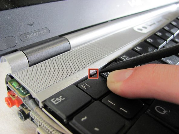
Push the tabs shown on both sides and the keyboard will pop up.
-
A small flat-head might help you push the tabs.
-
-
Este paso está sin traducir. Ayuda a traducirlo
-
Gently disconnect the ribbon cable by sliding down the tabs.
-
Gently take out the keyboard.
-
-
-
Este paso está sin traducir. Ayuda a traducirlo
-
Turn the securing screw on top of the CPU housing bracket counter-clockwise on the unlock position.
-
Gently lift the CPU out of the system with tweezers and set aside in a safe place.
-
-
Este paso está sin traducir. Ayuda a traducirlo
-
Remove the three screws from the front mouse panel.
-
Lift the mouse assembly just enough to access the connecting ribbon cable.
-
Lift the ribbon cable lock to remove the cable.
-
Carefully remove the mouse panel assembly and set aside.
-
-
Este paso está sin traducir. Ayuda a traducirlo
-
Remove the securing screw on the bottom left of the optical drive.
-
The IDE connector on the left will pop out.
-
-
Este paso está sin traducir. Ayuda a traducirlo
-
Disconnect the antennae from the wireless card.
-
Pull back the tabs on the right of the wireless card until the card disconnects and pops up.
-
Remove the wireless card and set aside.
-
-
Este paso está sin traducir. Ayuda a traducirlo
-
Remove the four screws from the underside of the computer. These screws are located underneath where the battery sits and secure the top keyboard panel.
-
To remove the panel below the screen, press up on the two tabs holding the panel in and lift up. The panel should pop off.
-
Before proceeding, remove all black tape holding down wires and other cabling.
-
-
Este paso está sin traducir. Ayuda a traducirlo
-
First pop off the antenna using a pair of tweezers.
-
Use a Philips screw driver to unscrew the screw holding the board in place.
-
Remove the board using a pair of tweezers.
-
-
Este paso está sin traducir. Ayuda a traducirlo
-
Remove the seven philips screws holding the speaker assembly in place.
-
Disconnect the ribbon cable located at the top left corner of the assembly.
Only 2 screws, the others come from the bottom and secure the plastic shield removed 2 steps before this,
also 1 of the marks is a push-button...
-
-
Este paso está sin traducir. Ayuda a traducirlo
-
To remove the VGA cable, lift up on the metal bracket and gently lift the connector off the logic board.
-
To remove the webcam cable, lift up the connector from the logic board gently.
-
-
Este paso está sin traducir. Ayuda a traducirlo
-
This is where your Hard Drive is located.
-
Remove the three harddrive securing screws.
-
The Serial ATA (SATA) hard drive is located where the yellow box indicates in the picture.
-
-
Este paso está sin traducir. Ayuda a traducirlo
-
Remove all screws holding the keyboard tray to the laptop.
-
Lift the cover off the console and set aside.
-
-
Este paso está sin traducir. Ayuda a traducirlo
-
Remove bluetooth, speaker, webcam assembly. This is one unit and will come out together.
-
-
Este paso está sin traducir. Ayuda a traducirlo
-
Unscrew the four securing screws, two on each side of the LCD.
-
Carefully remove the LCD
-
-
Este paso está sin traducir. Ayuda a traducirlo
-
Remove all the screws securing the keyboard tray.
-
Remove keyboard tray.
-
-
Este paso está sin traducir. Ayuda a traducirlo
-
Unscrew and remove the internal fan.
-
Unscrew and remove the logic board from the backing.
-


Equipo

Cal Poly, Team 25-89, Amido Spring 2010 Miembro de Cal Poly, Team 25-89, Amido Spring 2010
CPSU-AMIDO-S10S25G89
4 Miembros
63 Guías creadas
2 comentarios
Does this work with the PCG 9J5L