Qué necesitas
-
Este paso está sin traducir. Ayuda a traducirlo
-
The main components of this kit are:
-
TMR-IF33 wireless transmitter
-
IFR-33 wireless receiver
-
9V DC output AC adapter
-
Set of headphones
-
I'm not sure if this product was sold in North America, this one was purchased in Japan. In the second photo you can see the original packaging.
-
I do know that Sony used the same IR transmission system in some of its North American TVs - these components work with the wireless headphones that came with my old XBR TV.
-
-
Este paso está sin traducir. Ayuda a traducirlo
-
The transmitter has a stereo audio mini-jack input, stereo RCA jack inputs, and a 9V DC input jack. On the bottom there is a switch for normal/surround sound.
-
On the back you can see some keyed mounting holes for optional wall-mounting ofthe transmitter.
-
We'll take this transmitter apart first...
-
-
Este paso está sin traducir. Ayuda a traducirlo
-
First, remove the 3 screws in the recessed holes on the bottom of the transmitter using a Phillips #1 screwdriver.
-
-
Este paso está sin traducir. Ayuda a traducirlo
-
Once the screws are removed, you can lift off the bottom cover.
-
-
Este paso está sin traducir. Ayuda a traducirlo
-
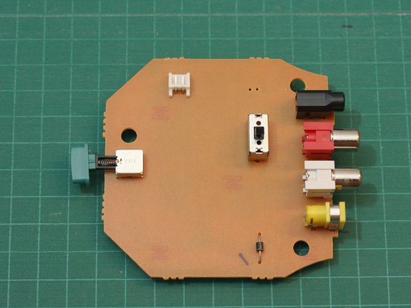
Carefully disconnect the connector shown from the circuit board. The wires go to the infrared LED array, which we'll see in a moment.
-
The circuit board on this side is very plain. The green button on the left is the power switch.
-
Hopefully there's more to the transmitter circuit than that lone diode visible on this side...
-
-
Este paso está sin traducir. Ayuda a traducirlo
-
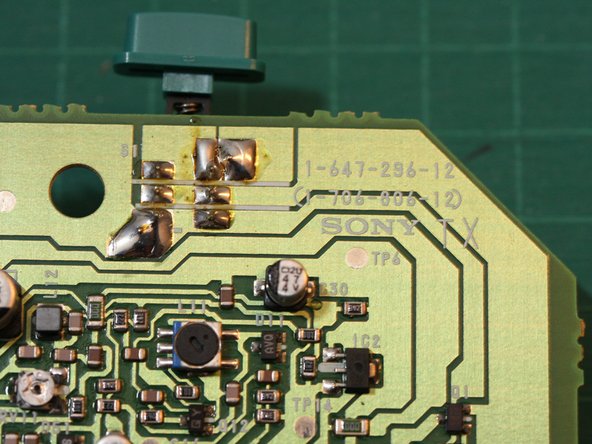
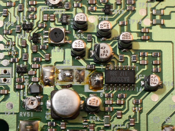
Here's the business side of the transmitter PCB, along with a couple closer views.
-
The transmitter consists of mainly discrete components. The lone IC in the 14 pin DIP packages is a BA3308F dual audio preamplifier.
-
-
-
Este paso está sin traducir. Ayuda a traducirlo
-
Next we'll open the housing for the IR transmitter array...
-
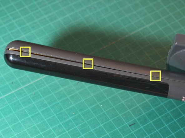
Using either your thumbnail or a spudger, carefully pry the housing open along the seam.
-
There are 3 hidden tabs on either side of the transmitter mast (see markers in 2nd photo). Pop these open carefully and the lens portion of the housing will come off.
-
-
Este paso está sin traducir. Ayuda a traducirlo
-
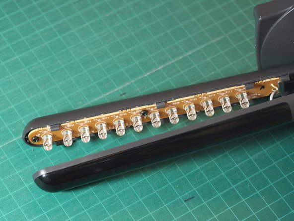
Here's the transmitter mast with the front lens/cover of the housing removed. Inside we see an array of infrared LEDs.
-
Next remove the 4 Phillips screws. Two of the screws fasten the metal hinge to the back half of the housing (one is partially obscured by the hinge in the first photo).
-
The other two screws fasten the LED circuit board to the back half of the housing.
-
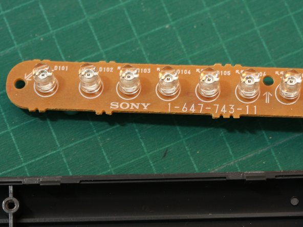
The third photo shows a closer view of some of the infrared LEDs. There are 12 LEDs in all. They emit no visible light - but did you know? the IR beam can be seen by most camcorders and digital cameras.
-
-
Este paso está sin traducir. Ayuda a traducirlo
-
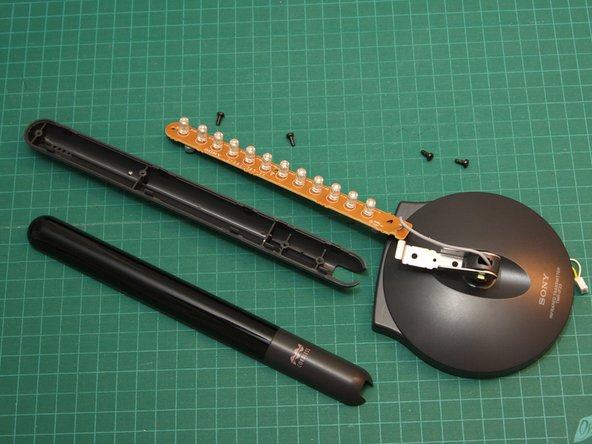
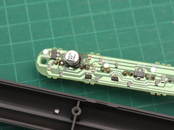
Here's the disassembled transmitter housing and a view of the rear side of the LED array circuit board.
-
Ho hum... all discrete components here, nothing too exciting.
-
That's it for the transmitter. Next up, the receiver...
-
-
Este paso está sin traducir. Ayuda a traducirlo
-
On the back, you'll find a swiveling clip and the battery compartment cover.
-
In use, the receiver can be clipped to your belt or shirt. The kit also comes with a lanyard (not shown) that let's you wear the receiver around your neck. Standard stereo earphones can be plugged into a jack at the bottom of the receiver.
-
The receiver is powered by a single AA battery.
-
-
Este paso está sin traducir. Ayuda a traducirlo
-
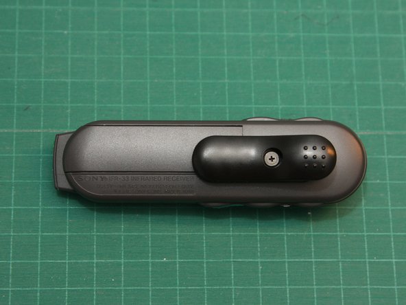
First, remove the screw in the center of the clip using a Phillips #0 screwdriver, and then remove the clip
-
-
Este paso está sin traducir. Ayuda a traducirlo
-
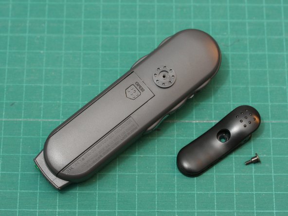
Next remove the battery cover.
-
This will reveal a screw which you can remove using a Phillips screwdriver
-
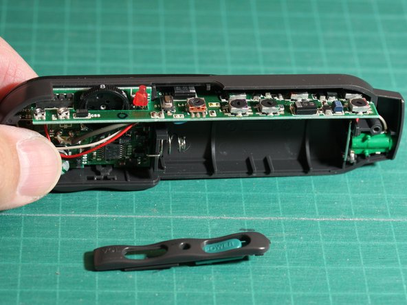
With this screw removed, you can now lift off the back half of the receiver case, revealing the circuitry inside.
-
-
Este paso está sin traducir. Ayuda a traducirlo
-
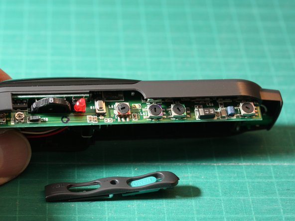
Carefully remove the bezel around the volume dial power switch and on/off indicator LED. Be careful not to lose the small power button cap which will come loose after removing the bezel
-
-
Este paso está sin traducir. Ayuda a traducirlo
-
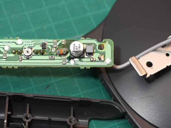
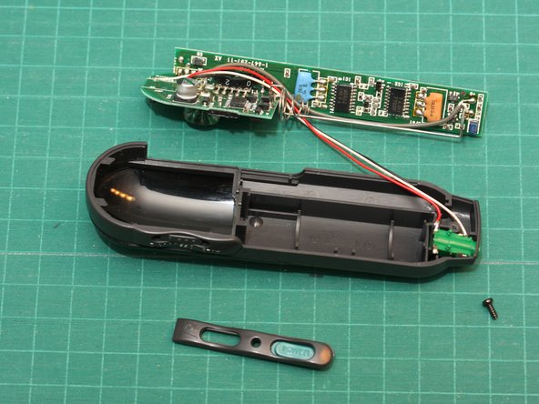
The receiver circuitry resides on two small circuit boards soldered together perpendicularly.
-
To remove the circuit board, first carefully pull the battery contact/spring up out of its mounting slot. This should free the circuit board.
-
The 3 wires connect the circuit board to the stereo earphone jack (green).
-
-
Este paso está sin traducir. Ayuda a traducirlo
-
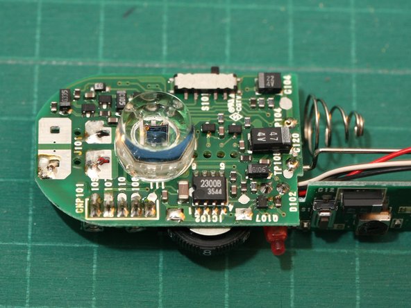
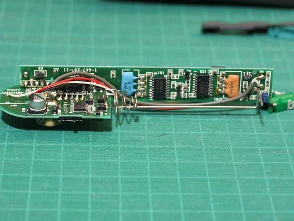
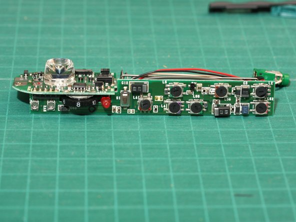
Here are a couple views of the receiver circuit board.
-
You can see the IR optical receiver under the large clear plastic lens. It's not obvious from the photos, but the cylindrical lens has a deeply concave front.
-
Once again, we notice mostly discrete components. The single IC in an 8 pin DIP package is a 2300B optocoupler chip.
-
-
Este paso está sin traducir. Ayuda a traducirlo
-
Finally, here are all the disassembled components.
-
That's it - I hope you found this interesting!
-


Un comentario
Bonjour, mon récepteur ne fonctionne plus. Je ne comprends pas l'anglais et ne suis pas capable en électronique !
Où pourrais-je l'envoyer pour réparation.
Merci beaucoup