Qué necesitas
-
-
-
Crossover / Gain
-
Power Supply and output FET's
-
Power Supply Transformer
-
Output Filters
-
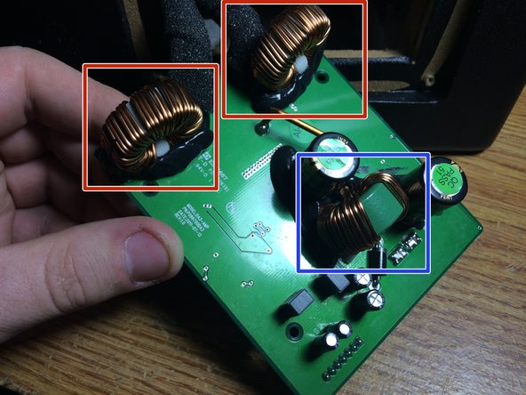
The 2 boards are held together by 4 screws on the edges of the PCB, gently pull them apart, they will only be held together by pin headers. Here you can see the 2 output filters and the power supply step up transformer
-
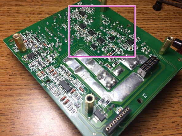
The board with the FEMALE pin headers is the front board with the plugs on it. the crossover network consists of JRC 4850's
-
-
-
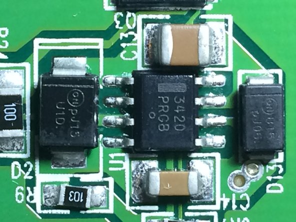
There are 4 of these "GA7E1S" FET's that i cant find any info on. i would assume by looking at the boards that 2 are the power supply and the other 2 are the outputs
-
There are NO heatsinks anywhere in this unit which i find amazing. but the FETS most likely use the massive copper planes on the board as the heatsink
-


23 comentarios
Nice, if you can do one on pulling the sub out that would be great. I think it might be glued in.
I have the 10” version of this sub but believe the amp is identical. I’d like to steal the amp from this to use in a new enclosure. Any idea how many ohms this could drive?
Im not sure, when i did this teardown i never thought about doing an ohms test on the driver. it might be a 2 ohm driver, but if you have the 10”, pop the plate amp out and stick a meter on the driver lol
I have a p300-12 , but the box shape is all wrong for my ‘07 FJ. What obstacles do you see after the teardown for transplanting the amp and sub into a custom fit box? Thanks in advance!
i dont see any issues with that idea. just when you get a new box get one thats similar in volume as the original and also sealed as i have no idea how the driver would perform in a vented enclosure. just keep the original rockford box so if you decide to sell it down the line you can reinstall it