Saltar al contenido principal

Qué necesitas

Este desmontaje no es una guía de reparación. Para reparar tu RCA RP3715A, utiliza nuestros manuales de servicio .

  1. RCA Radio Alarm Clock Teardown, RCA Radio Alarm Clock Teardown: paso 1, imagen 1 de 3 RCA Radio Alarm Clock Teardown, RCA Radio Alarm Clock Teardown: paso 1, imagen 2 de 3 RCA Radio Alarm Clock Teardown, RCA Radio Alarm Clock Teardown: paso 1, imagen 3 de 3
    • The RCA RP3715A Radio Alarm Clock

    • Features: Wide digital display with green numbers, two alarm settings, an AM/FM radio, tuner dial, volume dial, voice reading, and auto dimmer.

    • Control Buttons Include: ON/OFF, WAKE 1, CANCEL, WAKE 2, REV, FWD, NAP, SLEEP, and SNOOZE.

  2. RCA Radio Alarm Clock Teardown: paso 2, imagen 1 de 2 RCA Radio Alarm Clock Teardown: paso 2, imagen 2 de 2
    • Prepare the Clock for Teardown:

    • Unplug the clock.

    • Remove the battery: On the back of the clock, press down on the top tab of the clear plastic battery compartment door and pull out. Disconnect the battery by pulling it off the leads. Set the battery aside.

    • Note: As in our case, there may not be a battery. A battery is only needed if the clock is used without being plugged in.

  3. RCA Radio Alarm Clock Teardown: paso 3, imagen 1 de 3 RCA Radio Alarm Clock Teardown: paso 3, imagen 2 de 3 RCA Radio Alarm Clock Teardown: paso 3, imagen 3 de 3
    • Remove the Screws on the Back Panel:

    • Lay the clock on its face.

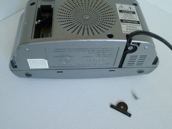
    • There are six screws total. Each is marked with a small arrow on the grey back panel:

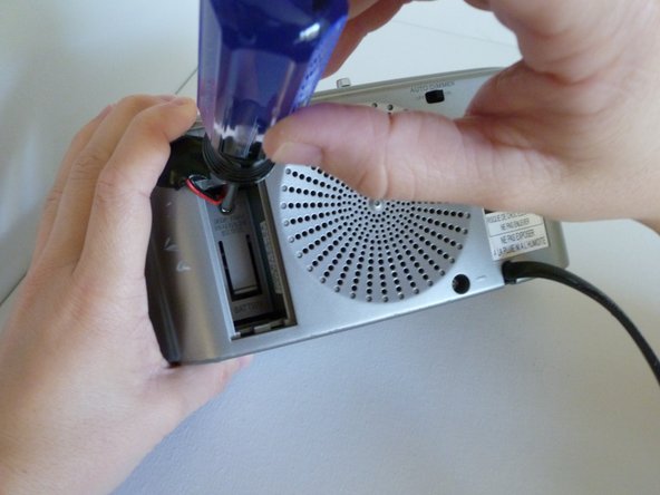
    • One is inside the battery compartment.

    • Three are on the back panel around the speaker.

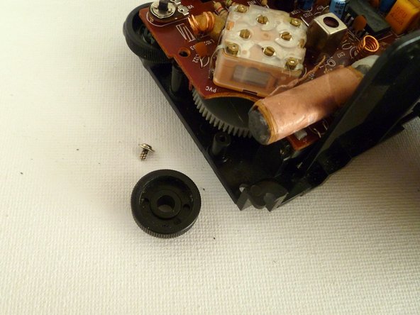
    • Two are at the base of the clock, on the lower left and right edges of panel (these two have longer screws).

  4. RCA Radio Alarm Clock Teardown: paso 4, imagen 1 de 3 RCA Radio Alarm Clock Teardown: paso 4, imagen 2 de 3 RCA Radio Alarm Clock Teardown: paso 4, imagen 3 de 3
    • Remove the Power Cable Strain Relief:

    • Remove the screw and metal bracket lying over the power cord on the base of the clock.

    • Gently pull the power cord out of the slot.

  5. RCA Radio Alarm Clock Teardown: paso 5, imagen 1 de 3 RCA Radio Alarm Clock Teardown: paso 5, imagen 2 de 3 RCA Radio Alarm Clock Teardown: paso 5, imagen 3 de 3
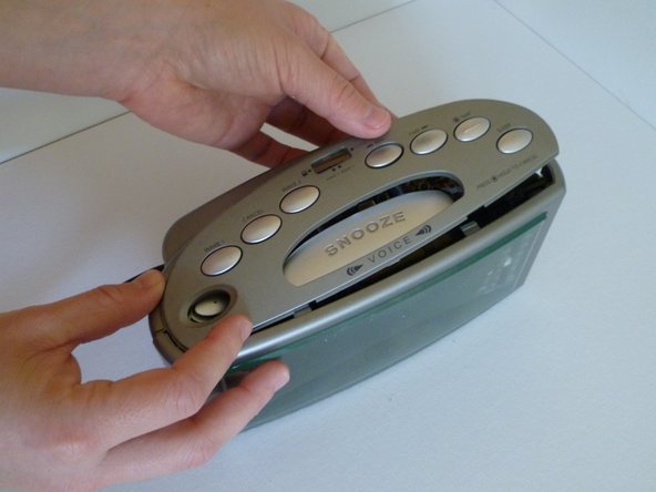
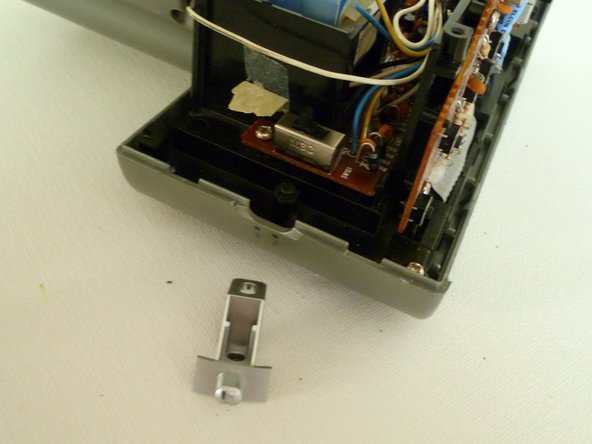
    • Release the Top Panel and Control Buttons:

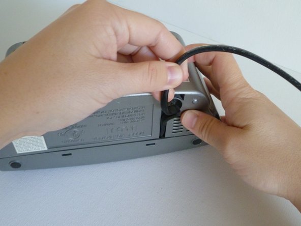
    • Still on the underside of the clock, press the two plastic release tabs at the seam between the front and back panels.

    • Note: You may need the help of a flathead screwdriver if you can’t release the tabs with your fingers.

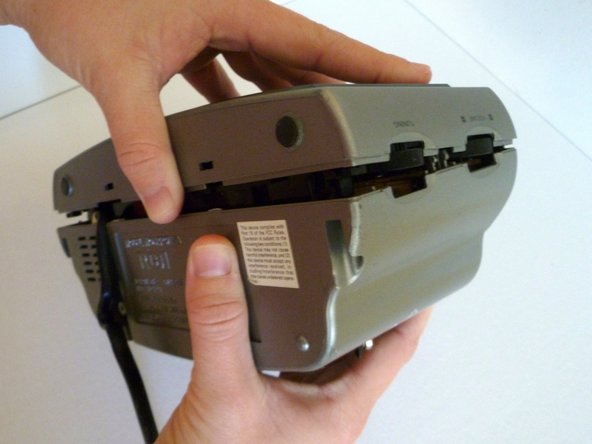
    • If you feel a snag, check the following seven internal release tabs. Generally, these are not an issue and the clock will easily pop apart releasing the top panel. If this is not the case, you can use a flathead screwdriver to release any stubborn tabs. The seven internal tabs are located:

    • Two are directly above and below the CANCEL button on the top panel.

    • Two are directly above and below the FWD button on the top panel.

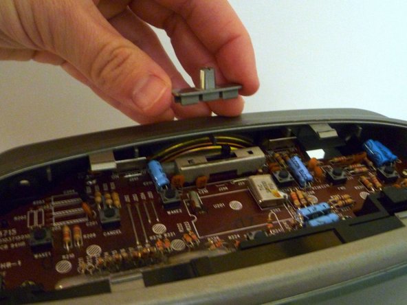
    • Two are directly above and below the AM/FM switch on the side of the clock.

    • One is between the TUNING and VOLUME dial on the other side of the clock.

  6. RCA Radio Alarm Clock Teardown: paso 6, imagen 1 de 3 RCA Radio Alarm Clock Teardown: paso 6, imagen 2 de 3 RCA Radio Alarm Clock Teardown: paso 6, imagen 3 de 3
    • Remove the Top Panel and Control Buttons:

    • Situate the clock upright.

    • Slide the top panel out from the release tabs and lift it off the clock.

    • Note: The SNOOZE and ON/OFF buttons are not connected to the top panel and may fall out.

    • Remove the grey plastic switch cover from the WAKE1/WAKE2 Switch on the top logic board.

  7. RCA Radio Alarm Clock Teardown: paso 7, imagen 1 de 3 RCA Radio Alarm Clock Teardown: paso 7, imagen 2 de 3 RCA Radio Alarm Clock Teardown: paso 7, imagen 3 de 3
    • Separate the Back Panel:

    • Lay the clock on its face and gently lift off the back panel.

    • Pull the battery leads through the hole in the back of the battery compartment.

    • Note: Be gentle! The unit will not come all the way apart because the speaker is still attaching the back panel to the clock’s main logic board.

  8. RCA Radio Alarm Clock Teardown: paso 8, imagen 1 de 2 RCA Radio Alarm Clock Teardown: paso 8, imagen 2 de 2
    • Remove the AM/FM Switch Button:

    • Slide off the grey plastic AM/FM switch button on the left side of the clock. It should be loose and practically fall out.

  9. RCA Radio Alarm Clock Teardown: paso 9, imagen 1 de 3 RCA Radio Alarm Clock Teardown: paso 9, imagen 2 de 3 RCA Radio Alarm Clock Teardown: paso 9, imagen 3 de 3
    • Remove the Speaker:

    • Remove the two screws and metal brackets holding the speaker to the back panel.

    • Using a flathead screwdriver, gently pry the speaker off the back panel.

    • Note: The speaker is lightly glued in place.

    • The back panel is now free.

  10. RCA Radio Alarm Clock Teardown: paso 10, imagen 1 de 3 RCA Radio Alarm Clock Teardown: paso 10, imagen 2 de 3 RCA Radio Alarm Clock Teardown: paso 10, imagen 3 de 3
    • Remove the Bezel Panel and Display Window:

    • Remove the two screws holding the front bezel panel in place.

    • Note: These screws are located at the inside top corners of the front grey bezel panel.

    • Gently remove the front grey bezel panel and separate the clear plastic display window.

  11. RCA Radio Alarm Clock Teardown: paso 11, imagen 1 de 3 RCA Radio Alarm Clock Teardown: paso 11, imagen 2 de 3 RCA Radio Alarm Clock Teardown: paso 11, imagen 3 de 3
    • Remove the Ten Screws on the Logic Boards:

    • Place the clock on its base.

    • Remove the five screws on the top logic board.

    • Flip the clock onto its face.

    • Remove the five screws on the main logic board.

    • Note: One of the screws on the main logic board is hidden on the outside of the power supply, as illustrated with the purple box.

  12. RCA Radio Alarm Clock Teardown: paso 12, imagen 1 de 3 RCA Radio Alarm Clock Teardown: paso 12, imagen 2 de 3 RCA Radio Alarm Clock Teardown: paso 12, imagen 3 de 3
    • Remove the Tuning Dial:

    • Place the clock on its face.

    • Unscrew the black tuning dial located just below the main logic board and remove it.

    • Note: You will need to gently lift the logic board next to the black tuning dial to get it out.

    • This frees the grey tuner wheel beneath it so that the main logic board can come out.

  13. RCA Radio Alarm Clock Teardown: paso 13, imagen 1 de 3 RCA Radio Alarm Clock Teardown: paso 13, imagen 2 de 3 RCA Radio Alarm Clock Teardown: paso 13, imagen 3 de 3
    • Free the Power Supply/Transformer:

    • Release the black tab on the left of the power supply.

    • Gently lift the power supply out and away from the black casing.

    • Rest the power supply, still attached, outside the clock casing.

  14. RCA Radio Alarm Clock Teardown: paso 14, imagen 1 de 3 RCA Radio Alarm Clock Teardown: paso 14, imagen 2 de 3 RCA Radio Alarm Clock Teardown: paso 14, imagen 3 de 3
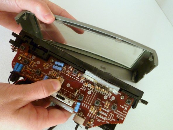
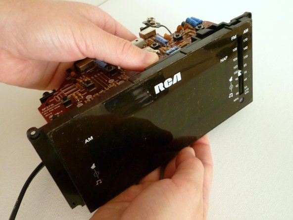
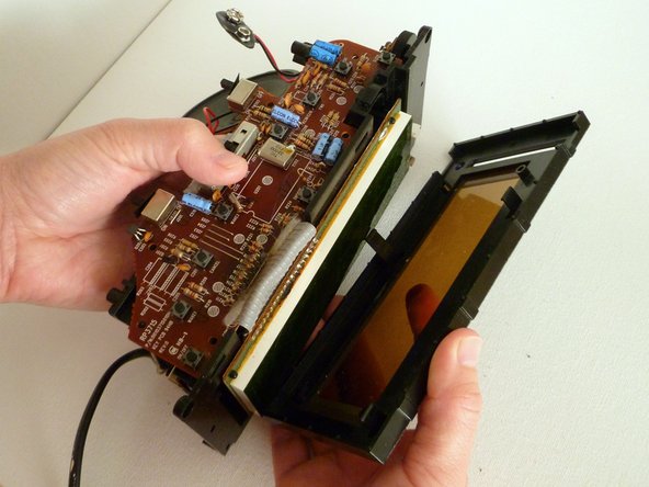
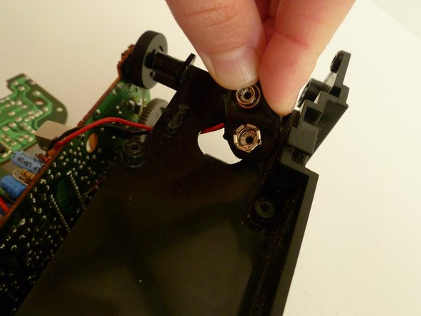
    • Remove the Tinted Digital Display Window:

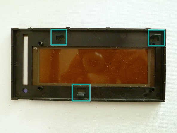
    • The tinted display window is held in place by tabs on the back of the tinted display window. Two tabs are located at the top and one tab is on the bottom as illustrated.

    • Release the two top tabs and pull the tined display window away from the casing.

  15. RCA Radio Alarm Clock Teardown: paso 15, imagen 1 de 3 RCA Radio Alarm Clock Teardown: paso 15, imagen 2 de 3 RCA Radio Alarm Clock Teardown: paso 15, imagen 3 de 3
    • Peel the Digital Display and Top Logic Board off the Casing:

    • Release the bottom tab on the digital display.

    • Lift the display off the four plastic pins at its corners.

    • Peel the digital display off the casing.

    • Continue peeling the top logic board off the casing.

  16. RCA Radio Alarm Clock Teardown: paso 16, imagen 1 de 3 RCA Radio Alarm Clock Teardown: paso 16, imagen 2 de 3 RCA Radio Alarm Clock Teardown: paso 16, imagen 3 de 3
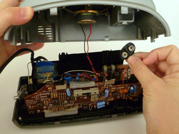
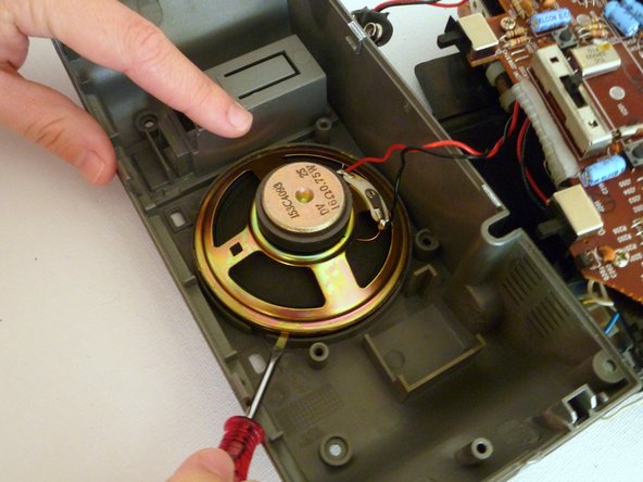
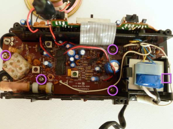
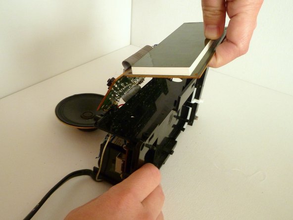
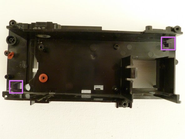
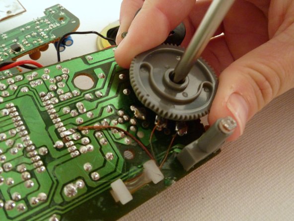
    • Separate the Digital Display and Logic Boards from the Casing:

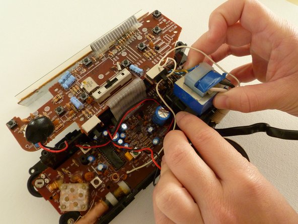
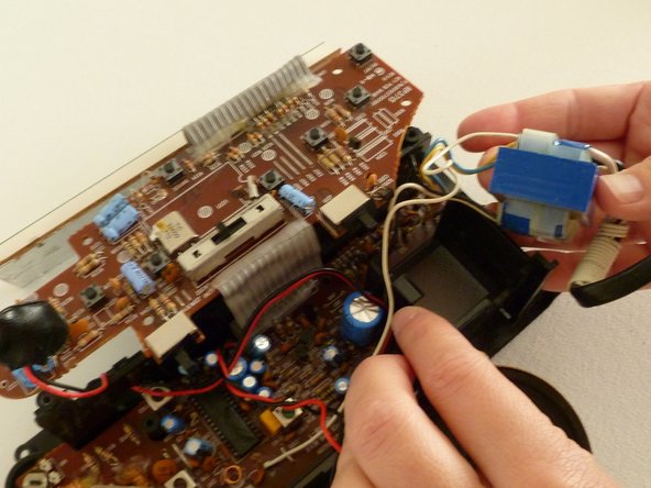
    • With the digital display and top logic board loose, place the casing face down with the main logic board facing up.

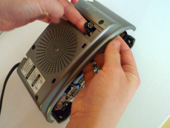
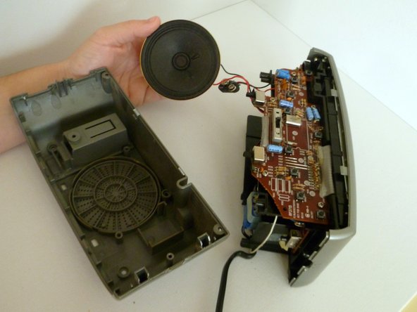
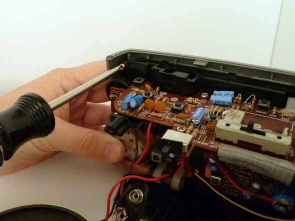
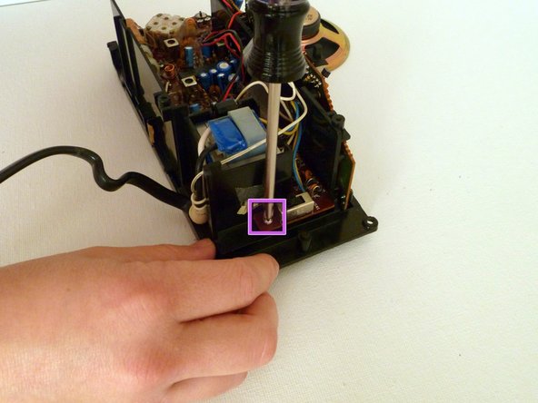
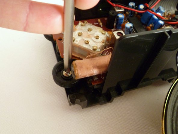
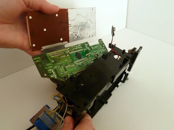
    • Release the two tabs holding the main logic board on the back casing. These tabs are located on the upper right and lower left corners of the casing.

    • Gently remove the main logic board from the casing.

    • Be Careful! The battery leads may get caught on the casing. You will need to help feed them through the circular hole on the casing.

  17. RCA Radio Alarm Clock Teardown: paso 17, imagen 1 de 2 RCA Radio Alarm Clock Teardown: paso 17, imagen 2 de 2
    • Remove the Tuner Wheel:

    • Unscrew and remove the grey tuner wheel from the back side of the main logic board.

  18. RCA Radio Alarm Clock Teardown: paso 18, imagen 1 de 1
    • The Clock Deconstructed

    • This is as far as the clock can be deconstructed without cutting wires or requiring soldering to reassemble.

    • Here is the entire clock deconstructed.

  19. RCA Radio Alarm Clock Teardown: paso 19, imagen 1 de 2 RCA Radio Alarm Clock Teardown: paso 19, imagen 2 de 2
    • Mini-Tour of the Main Logic Board

    • The main logic board hosts the radio components of the clock.

    • Internal Antenna

    • Tuning Screws

    • Inductor Coils

    • Power Supply/Transformer

  20. RCA Radio Alarm Clock Teardown: paso 20, imagen 1 de 2 RCA Radio Alarm Clock Teardown: paso 20, imagen 2 de 2
    • Mini-Tour of the Top Logic Board

    • The top logic board hosts the clock and control components.

    • Clock Crystal

    • Control Buttons

Equipo

HMD Global Miembro de HMD Global

Community

8 Miembros

1 Guía escrita

Un comentario

Thanks so much for posting this tear down. I love this clock, but one of the alarm buttons went out and I wasn't sure how to fix it. This showed me all the information I needed even though it wasn't specifically about that issue. Now I can use both alarms again!

stephenstrange - Contestar

Agregar Comentario

Ver Estadísticas:

Ultimas 24 horas: 0

Ultimos 7 días: 4

Ultimos 30 días: 13

Todo El Tiempo: 6,490