Saltar al contenido principal

Este teardown está en en curso – Recarga periódicamente para ver los cambios más recientes!

Qué necesitas

  1. M6013 Capacitor Meter Teardown, Removing Battery: paso 1, imagen 1 de 2 M6013 Capacitor Meter Teardown, Removing Battery: paso 1, imagen 2 de 2
    • Remove the circled screw

    • Remove battery case and batteries

  2. M6013 Capacitor Meter Teardown, Removing Case: paso 2, imagen 1 de 3 M6013 Capacitor Meter Teardown, Removing Case: paso 2, imagen 2 de 3 M6013 Capacitor Meter Teardown, Removing Case: paso 2, imagen 3 de 3
    • Remove circled screws

    • Pull case apart

    • Watch out for buttons, they will fall out easily.

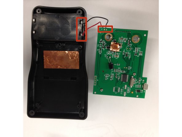
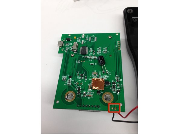
  3. M6013 Capacitor Meter Teardown, Remove Circuit Board: paso 3, imagen 1 de 3 M6013 Capacitor Meter Teardown, Remove Circuit Board: paso 3, imagen 2 de 3 M6013 Capacitor Meter Teardown, Remove Circuit Board: paso 3, imagen 3 de 3
    • Remove circled screws

    • Be careful when removing the circuit board, the battery cable is still connected.

    • Unsolder the square locations either on the circuit board or the case to fully remove the circuit board

    Good morning, community, I need help to identify the value of resistors R10, R6, R7, R1 of my m6013 that broke down by mistake.

    Ing_cor - Contestar

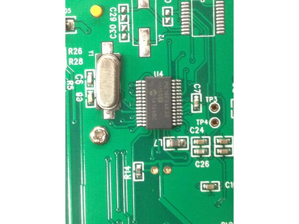
  4. M6013 Capacitor Meter Teardown, Microprocessor: paso 4, imagen 1 de 2 M6013 Capacitor Meter Teardown, Microprocessor: paso 4, imagen 2 de 2
    • Location of microprocessor

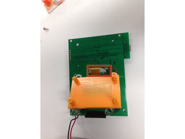
  5. M6013 Capacitor Meter Teardown, Remove Display: paso 5, imagen 1 de 2 M6013 Capacitor Meter Teardown, Remove Display: paso 5, imagen 2 de 2
    • Remove the cable connector

    • Remove Display

Ted Hsueh

Miembro Desde 09/20/12

170 Reputación

3 Guías creadas

Equipo

Cal Poly, Team 16-56, Forte Fall 2012 Miembro de Cal Poly, Team 16-56, Forte Fall 2012

CPSU-FORTE-F12S16G56

5 Miembros

13 Guías creadas

2 comentarios

Add some specs on start and foto of the unit ....

Mateusz - Contestar

Hello everyone, can someone help me identify the regulator that is in the printed circuit of this capacimeter identified with "U1" and the diode "D1" I appreciate any information.

CHUCHOX - Contestar

Agregar Comentario

Ver Estadísticas:

Ultimas 24 horas: 0

Ultimos 7 días: 2

Ultimos 30 días: 15

Todo El Tiempo: 614