Qué necesitas
-
-
Un tornillo Phillips PH1 ubicado en la parte posterior para quitar la tapa de la batería.
-
-
-
Tres tornillos Tri-point Y0 se encuentran debajo de la tapa de la batería.
-
Luego la placa frontal roja/blanca sale por el frente.
-
-
-
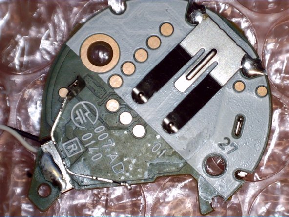
La PCB se coloca sobre tres soportes de plástico con solo la presión de los tornillos posteriores para fijarla en su lugar.
-
La placa de circuito impreso y el motor de vibración se pueden extraer con solo una mínima presión.
-
-
-
-
Botón de función ubicado en el centro
-
LED multicolor al lado del botón
-


Un agradecimiento especial a estos traductores:
100%

¡ Francisco Javier Saiz Esteban nos está ayudando a reparar el mundo! ¿Quieres contribuir?
Empezar a traducir ›
18 comentarios
This post needs moar wisdom
Anybody able to spot a Pedometer?
There is no pedometer. It's just a Bluetooth clicker. Your phone's sensors track all movement.
What is the
"A1
HNG
SBJ"
chip in "step 6"?
I2C/SPI flash?
And.. what is in "Step 4" the chip? in between the capacitors and that "mostlikely MOSFETs for driving LEDs".
I'm looking at DA14580 modules on ebay:
http://www.ebay.com/sch/i.html?_from=R40...
And I tend to to say "let's try to clone this", the DA14580 has OTA programmable FLASH. :)
Last picture is most likely JTAG pogo contact points. For programming and testing. The board seems to be like 3-4+ layer board just based on the pictures. Also can't really tell you what chips those are with that quality of a picture. However the two little chips under the mounting hole on the picture in step 4 looks to be the DC Boost IC to keep constant voltage throughout the batteries life. The chip to the left of those boost converts is most likely the Bluetooth IC (just guessing by the location and the traces around it). Hope this helps :)