Introducción
This time around, it is time to open up an activity tracker, that seems fixable.. although you might be leaving a few melted plastic marks.
There is a very lengthy article here that writes about his UX on the B1 tracker.
You can also skip ahead to this table he had provided that listed down all the functions and features the B1 offers
Also, if you like to read further, Basis had written a whitepaper of its B1 product here.
Qué necesitas
-
-
Technical Specifications
-
1 MHz RISC 16 Bit MicroController, Active Mode @ 400uA
-
Ultra Low-Power Consumption at Standby Mode @ 1.3uA, and Off-Mode with RAM Retention @ 0.22uA
-
Sensors onboard: Optical blood flow; Galvanic Skin response (perspiration), Ambient Temperature, Body Temperature, 3-Axis Accelerometer
-
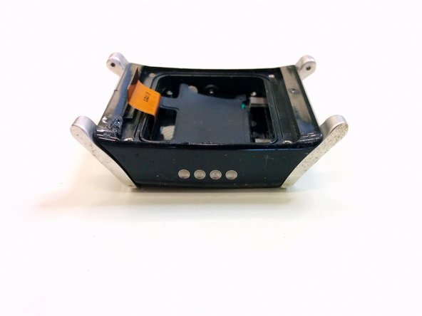
First, you begin by taking off the straps. . If you have taken out a watch strap before, it is a similar method
-
Flip the watch, use the plastic opening tool and slide into end of the strap, then push the spring contacts until the strap just breaks away from its catch
-
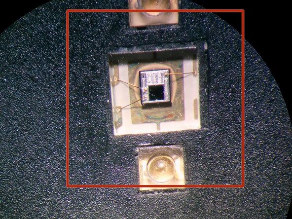
Independent electrodes to possibly modulate AC Signal onto your skin and measure at the receiving end. Possibly measuring impedance (thereby knowing how much you sweat)
-
-
-
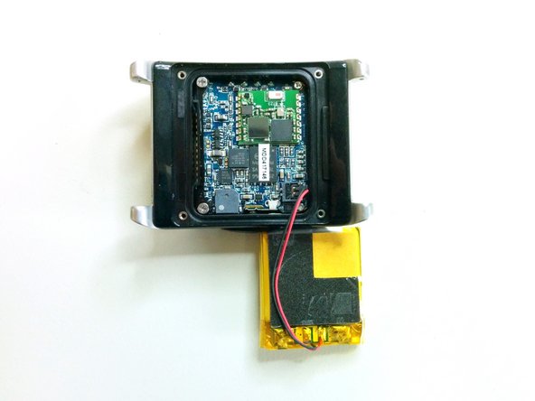
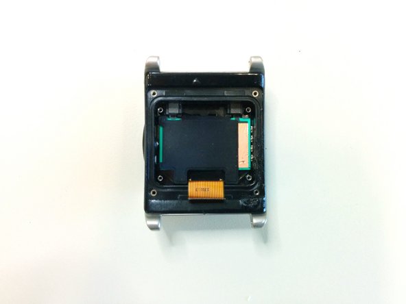
Remove the elastomeric (aka zebra) connector
-
Then pull the power plug away from its supply point to remove the battery
-
Unknown battery capacity
-
-
-
-
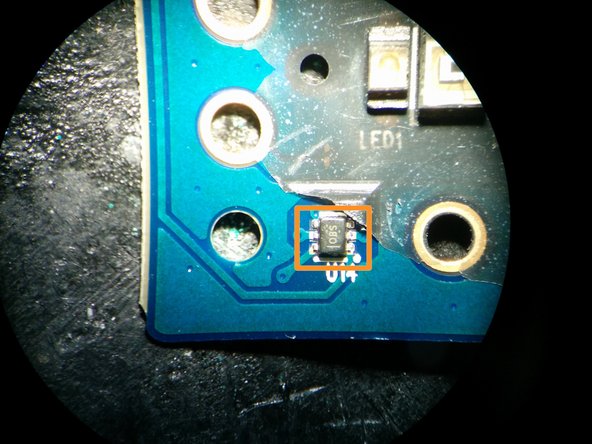
1st Temperature Sensor (Texas Instruments) TMP112 marked as OBS. This might be one of the sensors that detects the ambient temperature as it is positioned away from the human body
-
25P32V6G - ST 32MB NOR Serial Flash Memory
-
Analog Devices - ADXL335B, 3-Axis Accelerometer
-
Freescale MPR121 Proximity Capacitive Touch Sensor Controller (for the 4 capacitive touch buttons) as listed at this site & pictured here
-
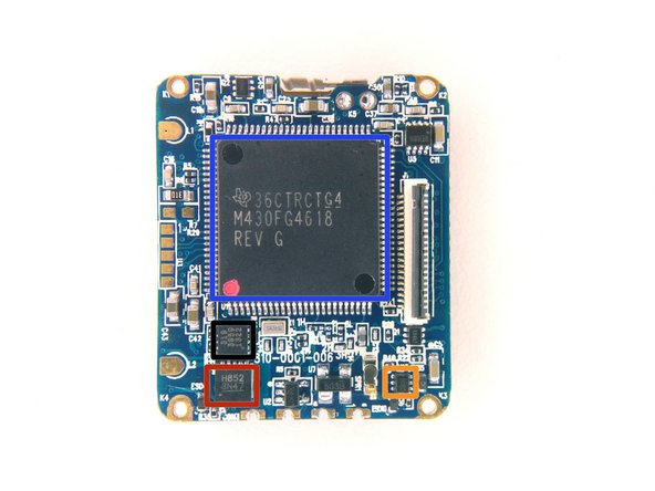
MSP430xG461x- Texas Instruments MSP430 family of ultralow-power mixed signal microcontroller. Built-in Temperature Sensor.
-
Unknown 31939591322
-
Unknown H852 3N47
-
-
-
I'm quite interested of what they have done here. Instead of doing their own RF design, they employed a module design. Too bad there is no way to give the RF Module company any publicity Edit - the module is BT23 from ampedrf
-
Cortex M3 - STM32F103C6; Low-density performance line, ARM-based 32-bit MCU with 16 or 32 KB Flash, USB, CAN, 6 timers, 2 ADCs, 6 communication interfaces. Built-in temperature sensor here
-
Unknown 2500D8, 90MT323 Bluetooth Transceiver Chip
-
Chip Antenna
-


4 comentarios
I don't see any mention of USB on the MSP430's data sheet, so those two unknown chips *might* be a USB-serial bridge and an EEPROM for the VID/PID/etc. They're right next to what seems to be an oscillator too.
I didn't separate the boards on mine so I couldn't get a good look, but my battery was marked: Cyber-Power CYL-352426 3.7V, 190mAh
Quick comment, the temperature sensors used in the device are not the ones embedded in the microcontrollers but the 2 TMP112. These are the ICs with SOT563 package marked as OBS.
Thanks Luis!, I will update the page shortly. PS; you can update this page too. I've set edit reputation to 0 should the general public discover more information than me