Saltar al contenido principal

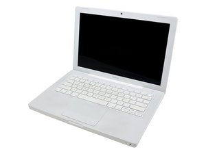
Modelo A1181: procesador Core 2 Duo de 1.83, 2, 2.1, 2.13, 2.16, 2.2 o 2.4 GHz

Preguntas 1203 Ver todo

Trying to replace a blown capacitor

Hello all,

I'm new to Macs, but I just picked up a Macbook for super cheap due to 3 blown capacitors. I just got a brand new soldering station, the Weller WES51, with a very small tip, so I've got most of the necessary equipment. The blown capacitors in question are SMD, very very small. One of the capacitors I'm having trouble with. I desoldered it, but I'm not sure how the orientation should be for the new one. I've posted a picture where it should be. It looks like the right pad is missing, but I'm not sure. Can I just solder one end of the capacitor to the ball at the end of the metal strip, as shown in the picture? The strip extends from beneath one of the pins on the keyboard connector. Can anyone confirm this? Or, is there any way someone could post a high-resolution image from their Macbook white logic board?

Thanks for any help!

Contestado! Ver respuesta Yo también tengo este problema

Es esta una buena pregunta?

Puntuación 2
2 comentarios

Hi, your picture(s) is/are not showing up. How do you know the 3 known bad components are capacitors or that they are bad? How did you choose and acquire your new parts to solder on? On the 2.4Ghz early 2008 board the only component with 2 connections, near the keyboard header is an inductor with a 402 package size. It has one trace coming from the sub-levels of the board and shares a trace with a pad for the keyboard socket. If you are trying to solder on this board without optics that you can allow you to see if a pad is missing or not you may not end up with a good deal - you could actually end up destroying the board. What is the last 3 characters of your laptop serial number?

- de

Thanks a ton for replying. Odd the pictures didn't appear. Here's a larger view http://tinypic.com/view.php?pic=21mceuo&... and a close view here http://tinypic.com/view.php?pic=4gnqdz&s....

I received the computer from a guy who damaged the computer himself. He had it open while it was on. He claimed he blew three capacitors after touching the keyboard (metal) to the motherboard. He pointed them out. They were obviously blown, they were physically burnt. All I have is his word, really.

The one component in question I wan't sure if it was a capacitor. The other two appeared to be the little black-banded SMD capacitors. They were in a group of the same black banded capacitors and looked identical. I planned on unsoldering the black banded capacitors from a different, working board and using them to replace the burned ones. The last three serial numbers of the macbook is 0p1.

Even if there might not be a ton of hope for the board, I'd like to do my best to repair it.

Again, thanks so much for your help.

- de

Agregar un comentario

1 Respuesta

Solución Elegida

That is an inductor, not a capacitor. Since you are pulling the parts from another A1181 board it will have the correct Henries. It has no polarity, so orientation doesn't matter. From the closeup view I would say you are correct the pad is gone. You have your work cut out for you trying to repair that without a stereo microscope. I would suggest using a small Dremel grinding tool by hand to scrape the shellack/covering off the trace prior to the missing pad. That works better than a knife and you have less chances of ripping off part of the trace. Clean the exposed piece of trace by applying a small amount of flux to it and hitting it with a soldering iron. Then apply a small amount of solder to the cleaned copper trace. Now you can take a small sliver of copper foil (cut from a new copper pot scrubber) and attach it to the trace to rebuild your pad.

I am going to suggest you use solder paste instead of solder wire for fine work such as this repair. I would recomend using this or a similar product. You can apply small amounts of it with the tip of a tooth pick, hit it with the soldering iron, melts like butter - perfect solder joint, no blobs. This stuff makes soldering a whole new world. If you have the right stencils, you can even use it for reballing.

Edit to Show Pictures of No Stripe

Block Image

Block Image

Block Image

Fue útil esta respuesta?

Puntuación 6

8 comentarios:

Firstly: Correction--I should have been more clear. The other board--is NOT a macbook logic board. I was using this board to replace the capacitors. Obviously not the inductor. Do you have any idea where I could get my hands on an inductor rated at the correct Henries?

Secondly: Would it be safe enough to replace the two other blown capacitors with capacitors from this other spare board? I think they have the same capacitance--they're the black-banded ones.

Thirdly: Is there any way I could try to get the Macbook working again WITHOUT replacing the inductor for now? I know I would be without the trackpad/keyboard, but I want to see if I can at least get this thing to boot.

- de

I would not recommend just pulling things off another board and counting on them to work correctly. Can you post some pictures of them, like you did the other part. I should be able to get you the values of all of them.

- de

There are jumper pads near the fan that you can short to power this on without the keyboard. I'll get you pictures of those. It should fire up without the inductor. The keyboard socket amounts to 2 funny looking USP ports.

- de

I did see the power jumper pads earlier. Here is the macbook logic board, I've unsoldered two sets of the capacitors, as shown (their orientation was horizontal, same as the capacitors just above them and to the left.) http://i42.tinypic.com/qq5snk.jpg The capacitor closest to the edge of the board definitely had the black stripe, the one next to it was too badly charred to tell, but I thought there was a good chance that it was also black striped.

Here is the spare board, a logic board for a completely different computer. I circled sets of the black striped capacitors that I though I'd try to solder to the macbook logic board. http://i39.tinypic.com/14xkxsp.jpg

- de

I looked at the components that occupy the empty pads you have circled, on the same model board you have, under a microscope. Neither has a black line on it, nor are there any markings on the board to indicate what type of component it is. My LCR meter is down, I can't get a measurement off of them - without great hassle. I'll be getting another LCR meter in around the first of the year. I also have a couple of other flavors of the A1181 I can look at. I strongly advise you to not solder "just anything" in there. If I haven't got back with you about this by the new year, bump me on this to remind me. I would also like to add, the person you purchased this board from is NOT an honest person. There is no way for the metal from the keyboard to have touched ANY of these components without basically destroying the upper case and intentionally trying to make the metal touch the board. You may want to consider returning them the board or getting some of your money back. I'd pay $20 for the board on a gamble - most.

- de

Mostrar 3 comentarios más

Agregar un comentario

Añadir tu respuesta

Evan estará eternamente agradecido.
Ver Estadísticas:

Ultimas 24 horas: 0

Ultimos 7 días: 0

Ultimos 30 días: 1

Todo El Tiempo: 2,991